Straight rebar collecting and bundling system

A technology of steel bars and straight strips, which is applied to the parts and packaging of strapping machines, can solve the problems of high labor intensity, fluctuations in production technology, and high labor costs, so as to reduce labor intensity, increase collection speed, and reduce labor costs. Effect

Pending Publication Date: 2018-10-02
ANYANG HELI CHUANGKE METALLURGY NEW TECH RES & DEV
View PDF11 Cites 0 Cited by
  • Summary
  • Abstract
  • Description
  • Claims
  • Application Information

AI Technical Summary

Problems solved by technology

[0002] The main method in the current collection and packaging section of straight steel bars is to use the steel turning machine to collect the wire rods cut to length in the side collection tank, and then use manual operations to carry out follow-up work. When the steel turning machine turns over the steel bars , the steel bars fall into the collection tank along a fixed curve, and the steel bars turn over into the collection tank and "pile up like a mountain". It is necessary to manually spread out the steel bars to fill the collection tank; Bundling requires manual operation of a baler to bale, so the labor intensity of the workers in the current collection and packaging section of straight steel bars is very high, requiring manual cooperation and cooperation, the labor cost is high, and the heated steel bars are also likely to cause injuries to workers; there are more The most fatal thing is that if manual work is used, the production line needs to slow down at many manual participation points, which leads to the following problems: First, the overall

Method used


Image

  • Straight rebar collecting and bundling system
  • Straight rebar collecting and bundling system
  • Straight rebar collecting and bundling system

Examples


Example Embodiment

[0018] In order to more fully explain the implementation of the present invention, an implementation example of the present invention is provided. These implementation examples are merely illustrative of the present invention, and do not limit the scope of the present invention.
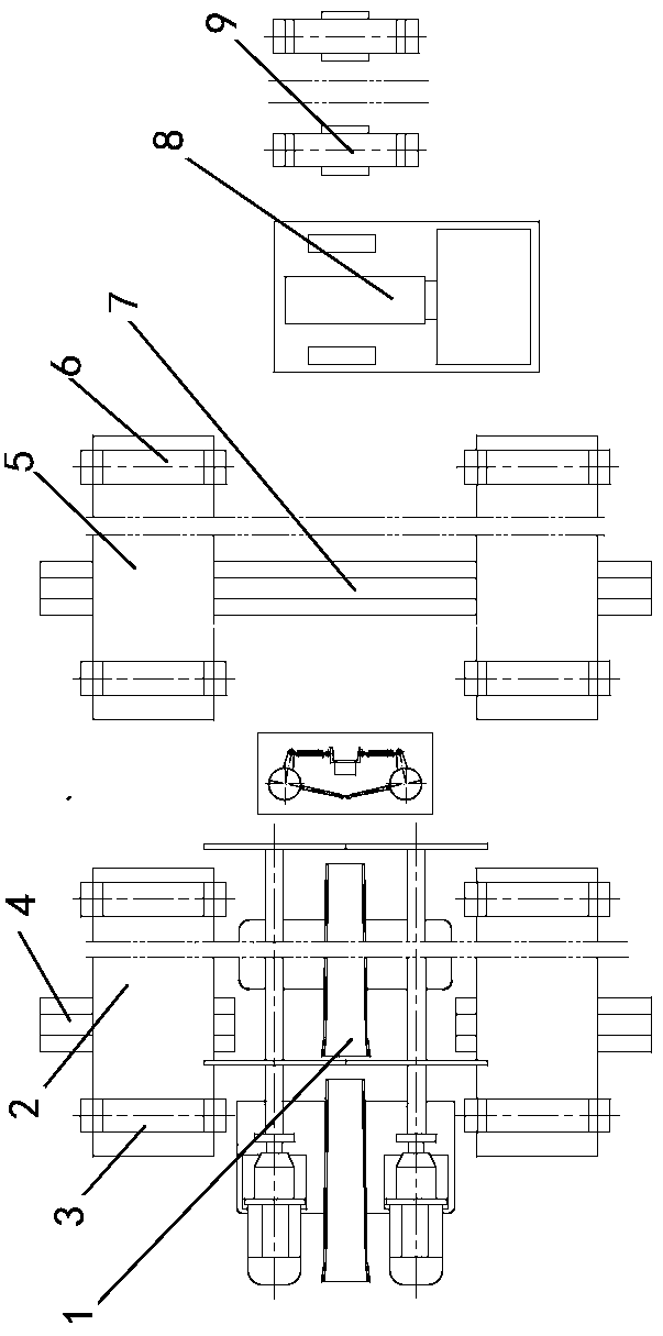
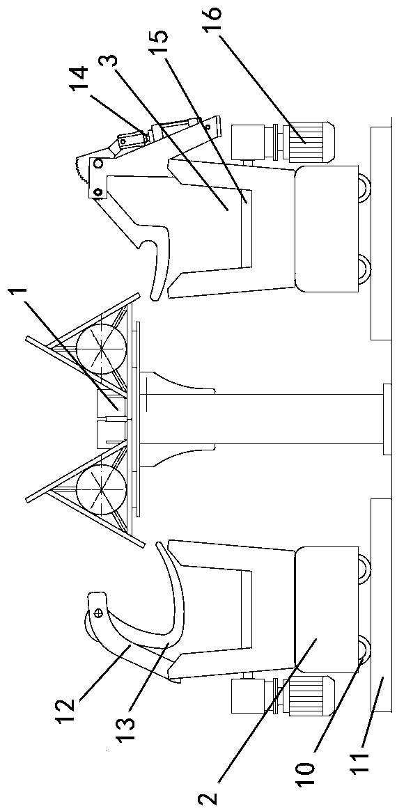
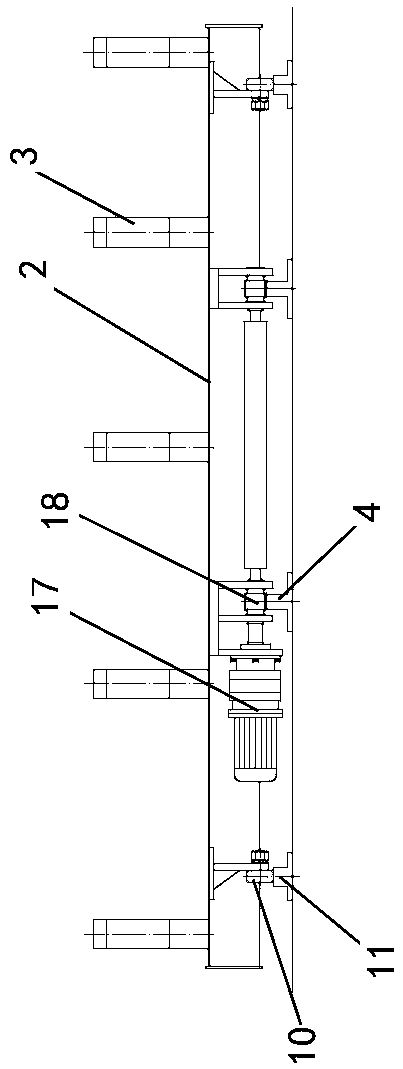
[0019] The present invention is further explained in detail in conjunction with the accompanying drawings. In the accompanying drawings, the marks are as follows: 1: steel turning machine; 2: collection trolley; 3: collection trough; 4: collection trolley drive rack; 5: transition trolley; 6: transition conveying Trough; 7: Transition trolley drive rack; 8: Bundling machine; 9: Bundle conveying trough; 10: Roller; 11: Guide rail; 12: Temporary support device; 13: V-shaped support; 14: Scrap removal device; 15: Collecting and conveying driving roller; 16: Driving roller driving device; 17: Motor; 18: Gear; 19: Rotating arm; 20: Air cylinder.

[0020] As shown in the figure, a straight steel bar collection...


PUM


Abstract

A straight rebar collecting and bundling system comprises a rebar collecting device, a rebar transition conveying device and a rebar bundling device. The rebar collecting device comprises a straight tilter and further comprises a reciprocating collection device arranged on the side wall of the tilter, the reciprocating collection device comprises multiple collection grooves in longitudinal arrangement, a collecting and conveying driving roller is mounted at the bottom of a U-shaped port of each of part or all of the collection grooves, and a collecting and conveying driving roller driving device is mounted on the side portion of each collection groove mounted with the corresponding collecting and conveying driving roller; a temporary supporting device is mounted on each of at least two collection grooves, the rebar transition conveying device comprises a transition conveying trolley arranged on the rear portion of the rebar collecting device, a reciprocating linear driving device is connected on the transition conveying trolley, the rebar bundling device is a bundler, and a bundled rebar conveying section is arranged behind the bundler. The system can realize full automation of rebar collecting and bundling.

Description

technical field [0001] The invention relates to rear-stage equipment in the production of straight steel bars, in particular to a collection and bundling system for straight steel bars, which belongs to the technical field of wire rod production equipment. Background technique [0002] The main method in the current collection and packaging section of straight steel bars is to use the steel turning machine to collect the wire rods cut to length in the side collection tank, and then use manual operations to carry out follow-up work. When the steel turning machine turns over the steel bars , the steel bars fall into the collection tank along a fixed curve, and the steel bars turn over into the collection tank and "pile up like a mountain". It is necessary to manually spread out the steel bars to fill the collection tank; Bundling requires manual operation of a baler to bale, so the labor intensity of the workers in the current collection and packaging section of straight steel...

Claims


Application Information

Patent Timeline
IPC IPC(8): B65B13/18B65B27/10B65B35/50B65B35/20
CPCB65B13/18B65B27/10B65B35/20B65B35/50
Inventor 夏维玺翟文
Owner ANYANG HELI CHUANGKE METALLURGY NEW TECH RES & DEV
Why Eureka
Try Eureka