Sludge separator

A separator and sludge technology, applied in sludge treatment, water/sludge/sewage treatment, dehydration/drying/concentrated sludge treatment, etc., can solve the problem of affecting structural stability, shortening service life, and inconvenient sludge transportation and other problems to achieve the effect of prolonging service life, improving work efficiency and improving sewage treatment rate

Inactive Publication Date: 2018-10-02
马鞍山纽盟知识产权管理服务有限公司
View PDF4 Cites 0 Cited by
  • Summary
  • Abstract
  • Description
  • Claims
  • Application Information

AI Technical Summary

Problems solved by technology

[0002] There will be a large amount of sludge in industrial production and daily life, which is inconvenient to transport, pollutes the environment, and wastes energy. During the sludge separation process, due to its excessive rotation speed, the maximum vibration is generated, which affects the stability of the structure and shortens the service life

Method used


Image

  • Sludge separator
  • Sludge separator

Examples


Embodiment Construction

[0013] The following will clearly and completely describe the technical solutions in the embodiments of the present invention with reference to the accompanying drawings in the embodiments of the present invention. Obviously, the described embodiments are only some of the embodiments of the present invention, not all of them. Based on the embodiments of the present invention, all other embodiments obtained by persons of ordinary skill in the art without making creative efforts belong to the protection scope of the present invention.

[0014] The invention provides a technical solution:

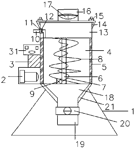
[0015] A sludge separator, comprising a base 1, the base 1 is provided with a drive motor 2, the drive motor 2 is connected to a speed stabilizer 3, the speed stabilizer 3 is connected to a CPU controller 31, and the CPU controller 31 is connected to the drive motor 2, Velocity meter 3, inner helical layer 7, outer helical layer 8, deflector 9, stop valve 17 and one-way valve 20, and velocity ...


PUM


Abstract

The invention relates to a sludge separator which comprises a base, wherein a driving motor is arranged on the base; the driving motor is connected with a speed stabilizer; the speed stabilizer is connected with a CPU controller; the speed stabilizer is connected with a separation chamber; a vibration damper plate is arranged inside the separation chamber; a support shaft is arranged inside the vibration damper plate; the support shaft is connected with an inner spiral layer; the inner spiral layer is connected with an outer spiral layer having a rotating direction opposite to that of the inner spiral layer; the support shaft is connected with a fluid director; the fluid director is connected with a drainage pipe; the drainage pipe is connected with a water outlet; a filter mesh is arranged on the water outlet; the water outlet is located in the interior of a buffer chamber; a cover plate is arranged at the top of the buffer chamber; a sealing ring is arranged in a junction position between the cover plate and the buffer chamber; two ends of the cover plate are fixed by flanges; an inlet is formed in the cover plate; a stop valve is arranged on the inlet; the bottom of the separation chamber is connected with a sludge collecting hopper; an outlet is formed in the bottom of the sludge collecting hopper; and a one-way valve is arranged at the outlet. The sludge separator providedby the invention has a simple structure, improves the accuracy, has zero error, improves the stability, enhances safety performance, improves the separation effect, improves the working efficiency, reduces pollutions, and has a recovery rate of greater than or equal to 98%.

Description

technical field [0001] The invention specifically relates to a sludge separator. Background technique [0002] There will be a large amount of sludge in industrial production and daily life, which is inconvenient to transport, pollutes the environment, and wastes energy. During the sludge separation process, due to its excessive rotation speed, the maximum vibration is generated, which affects the stability of the structure and shortens the service life. Contents of the invention [0003] The object of the present invention is a sludge separator to solve the existing technical problems. [0004] In order to achieve the above object, the present invention provides the following technical solutions: a sludge separator, including a base, a drive motor is arranged on the base, the drive motor is connected to a speed stabilizer, the speed stabilizer is connected to a CPU controller, and the speed stabilizer is connected to a Separation chamber, the inside of the separation ch...

Claims


Application Information

Patent Timeline
Patent Type & Authority Applications(China)
IPC IPC(8): C02F11/12
CPCC02F11/121
Inventor 张树霞
Owner 马鞍山纽盟知识产权管理服务有限公司
Why Eureka
Try Eureka