
Rotor assemblies, motors, automobiles

A component and rotor technology, applied in electric components, magnetic circuit rotating parts, electromechanical devices, etc., can solve the problems of blocked permanent magnet heat dissipation, blocking permanent magnet heat dissipation, permanent magnet high temperature demagnetization, etc., to improve output performance and heat dissipation. The effect of improving efficiency and improving heat dissipation capacity

Active Publication Date: 2020-11-24
GREE ELECTRIC APPLIANCES INC
View PDF14 Cites 0 Cited by
  • Summary
  • Abstract
  • Description
  • Claims
  • Application Information

AI Technical Summary

Problems solved by technology

[0002] New energy vehicles, as the future technical direction of reducing carbon emissions in the automotive field, will gradually replace fuel vehicles. New energy vehicles generally use permanent magnet synchronous motors. Permanent magnet synchronous motors have the advantages of high efficiency and low noise. Most of them use NdFeB permanent magnets. Magnets provide rotor excitation, but NdFeB is prone to thermal demagnetization at high temperatures, especially in the harsh operating environment of automotive drive motors. At present, the heat dissipation of the rotor is only achieved by the air in the motor to the motor stator and motor housing, while the permanent magnet There is a gap between it and the rotor core, and this gap is usually left untreated or glued. If it is not treated, the heat of the permanent magnet can only be dissipated through the air in the gap, and the efficiency is extremely poor. When glue is used During the treatment, the heat dissipation of the permanent magnets is obviously blocked. In the process of motor design, the problem of demagnetization of the permanent magnets of the rotor is mainly focused on. Demagnetization will occur, which will undoubtedly increase the production cost of the motor
[0003] In addition, for the fixing of the permanent magnets in the permanent magnet rotor assembly, the glue filling process or the plastic sealing of the rotor is mostly used at present. The use of the glue filling process will seriously hinder the heat dissipation of the permanent magnets, and the high temperature is required when the plastic sealing process is used. It will lead to high-temperature demagnetization of permanent magnets, so how to effectively fix permanent magnets while avoiding high-temperature demagnetization is worthy of attention. Based on this, the present invention is proposed

Method used


Image

  • Rotor assemblies, motors, automobiles
  • Rotor assemblies, motors, automobiles
  • Rotor assemblies, motors, automobiles

Examples


Embodiment Construction

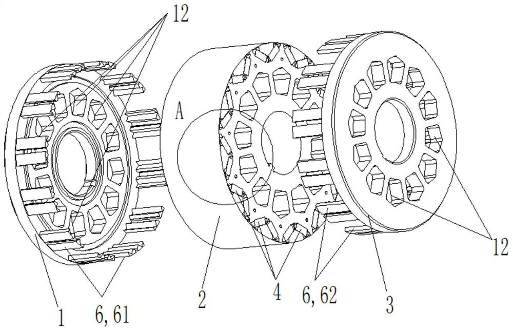
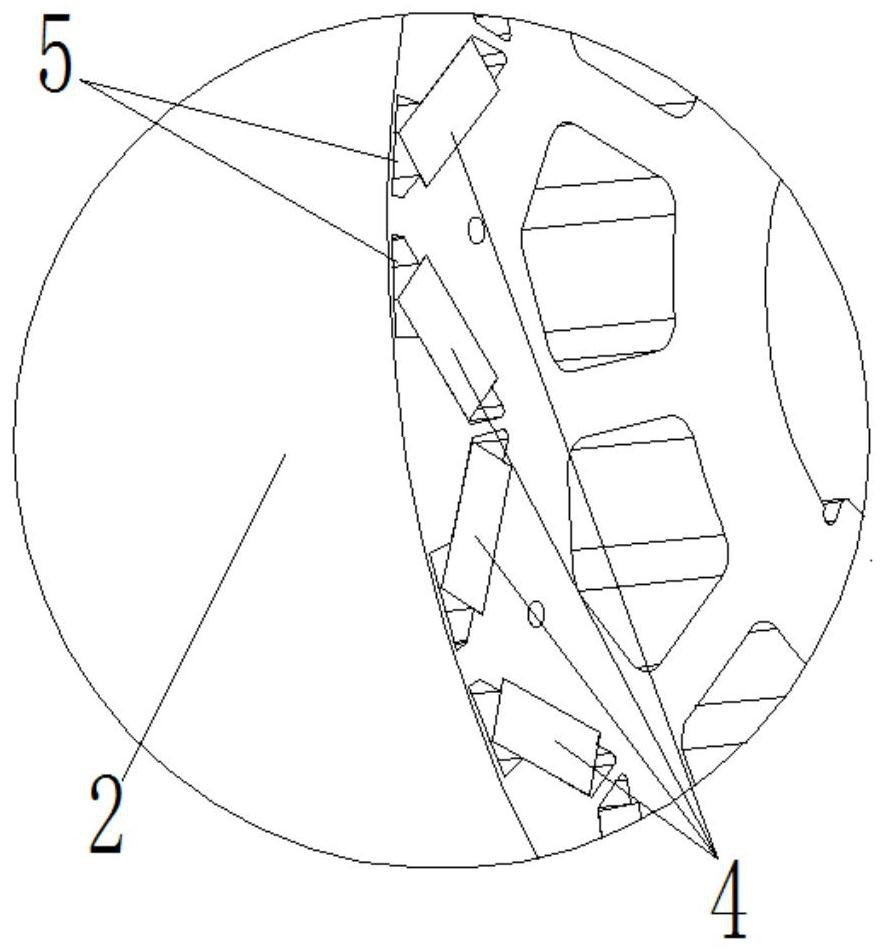
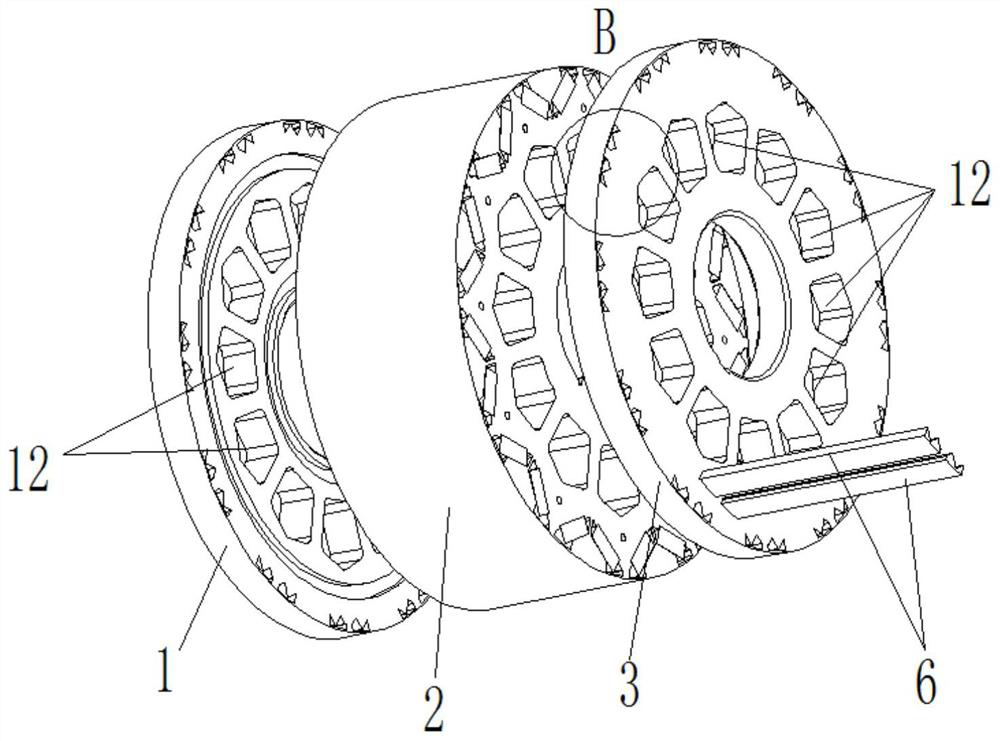
[0023] see in conjunction Figures 1 to 4 As shown, according to the embodiment of the present invention, a rotor assembly is provided, including a first baffle plate 1, a rotor core 2, and a second baffle plate 3 that are sequentially contacted and fitted. The rotor core 2 has a A plurality of extended through slots, a plurality of permanent magnets 4 are inserted in the plurality of through slots, and a plurality of permanent magnets 4 form a plurality of gap slots 5 with the rotor core 2 toward the outer peripheral wall of the rotor core 2, A heat dissipation guide bar 6 is inserted into several of the gap slots 5 , and at least one of the first baffle plate 1 or the second baffle plate 3 is connected to one end of the heat dissipation guide bar 6 . In this technical solution, since the heat dissipation guide bar 6 is inserted into the gap groove 5, at least a part of the heat dissipation guide bar 6 is in contact with the permanent magnet 4, and a part is in contact with t...


PUM


Abstract

The invention provides a rotor assembly, a motor and an automobile. The rotor assembly comprises a first baffle, a rotor iron core and a second baffle which are in contact and matched in sequence; a plurality of through grooves which extend in the axial direction are formed in the rotor iron core; a plurality of permanent magnets are inserted in the multiple through grooves; a plurality of gap grooves are formed between one sides of the periphery walls, towards the rotor iron core, of the multiple permanent magnets and the rotor iron core; heat dissipation conducting bars are inserted in the multiple gap grooves; and at least one of the first baffle or the second baffle is connected with one ends of the heat dissipation conducting bars. According to the rotor assembly, the motor and the automobile disclosed in the invention, heat dissipation of the rotor iron core and the permanent magnets can be ensured forcefully, temperature rise of the rotor iron core and the permanent magnets canbe controlled effectively, and a high-temperature demagnetizing phenomenon caused by an overhigh temperature of the permanent magnets can be lowered.

Description

technical field [0001] The invention belongs to the technical field of motors, and in particular relates to a rotor assembly, a motor and an automobile. Background technique [0002] New energy vehicles, as the future technical direction of reducing carbon emissions in the automotive field, will gradually replace fuel vehicles. New energy vehicles generally use permanent magnet synchronous motors. Permanent magnet synchronous motors have the advantages of high efficiency and low noise. Most of them use NdFeB permanent magnets. Magnets provide rotor excitation, but NdFeB is prone to thermal demagnetization at high temperatures, especially in the harsh operating environment of automotive drive motors. At present, the heat dissipation of the rotor is only achieved by the air in the motor to the motor stator and motor housing, while the permanent magnet There is a gap between it and the rotor core, and this gap is usually left untreated or glued. If it is not treated, the heat o...

Claims


Application Information

Patent Timeline
Patent Type & Authority Patents(China)
IPC IPC(8): H02K1/27H02K9/22
CPCH02K1/276H02K9/22H02K2213/03
Inventor 郭长光张小波张芳贾金信李忠雨李广海汪汉新王泽业
Owner GREE ELECTRIC APPLIANCES INC
Learn More