Heat dissipation panel with variable-width water channels

A cooling plate and variable width technology, applied in the direction of cooling/ventilation/heating transformation, electrical components, electrical equipment structural parts, etc., can solve the problems of temperature difference between inlet and outlet, overheating, uneven heat dissipation, etc., and reduce the total pressure drop , uniform temperature distribution, good heat dissipation effect

Pending Publication Date: 2018-10-02
张家港首驱动力科技有限公司
View PDF1 Cites 0 Cited by
  • Summary
  • Abstract
  • Description
  • Claims
  • Application Information

AI Technical Summary

Problems solved by technology

If the liquid flow distance is too long, it will inevitably cause the temperature difference between the inlet and outlet, resulting in uneven heat dissipation or local overheating
At the same time, in a system with a large rated flow rate, the pressure drop of the S-shaped water channel will cause the flow rate to fail to reach the rated flow rate, resulting in overheating and damage to electronic equipment

Method used


Image

  • Heat dissipation panel with variable-width water channels
  • Heat dissipation panel with variable-width water channels
  • Heat dissipation panel with variable-width water channels

Examples


Embodiment

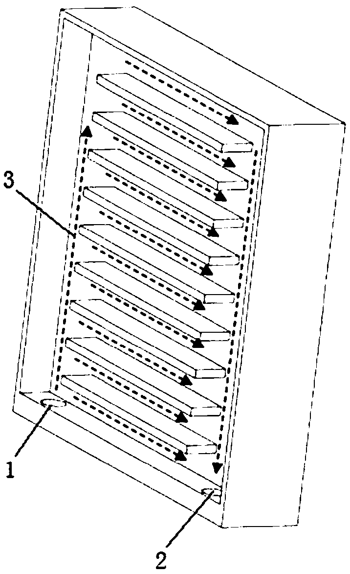
[0022] like figure 1 As shown, the existing radiator plate water channel includes coolant inlet 1, coolant outlet 2 and multiple "S-shaped" serial water channels 3 connected end to end. Due to the long distance of liquid flow, the temperature difference between the inlet and outlet is caused. This results in uneven heat dissipation or localized overheating.

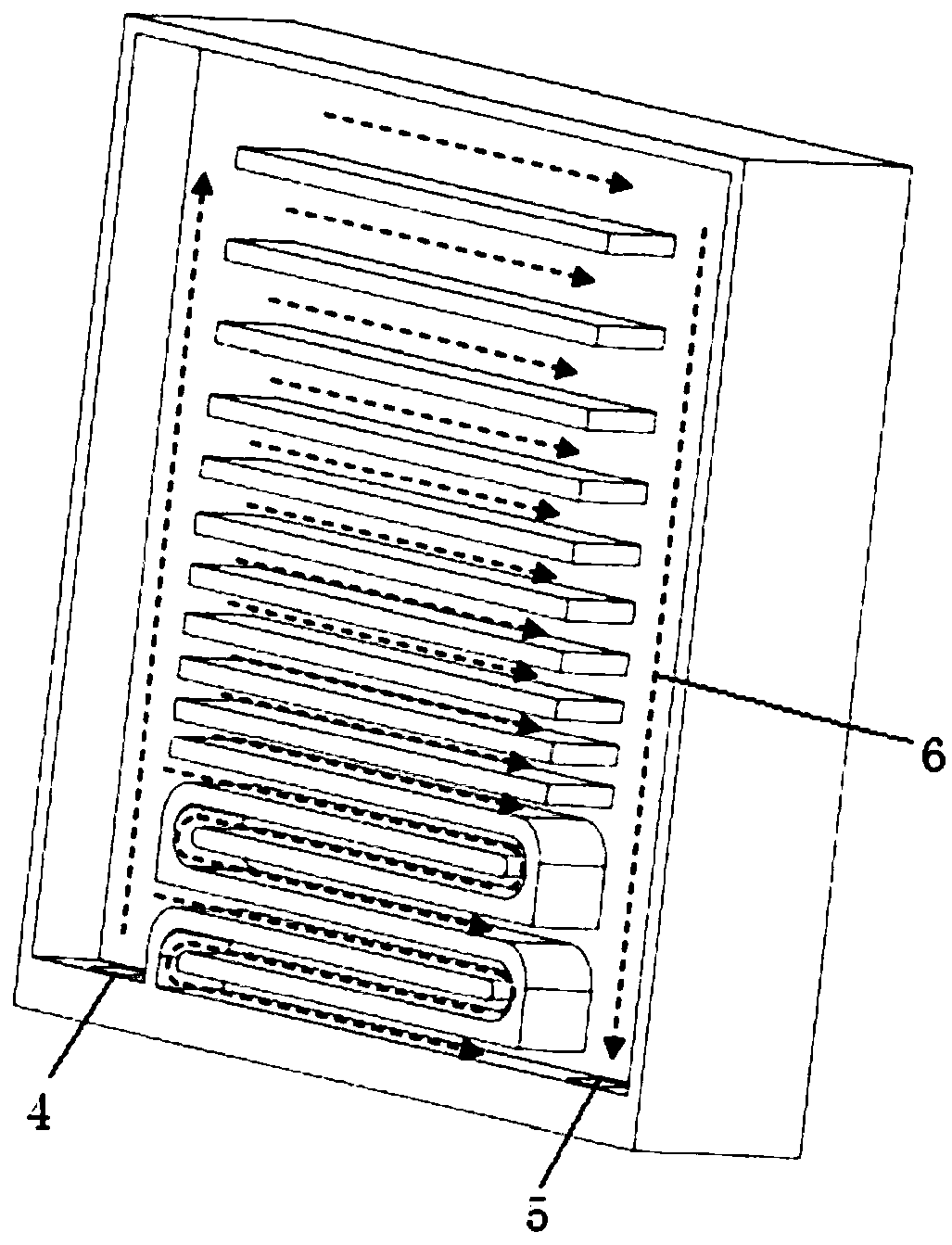
[0023] like figure 2 As shown, a heat dissipation plate of a variable-width water channel of the present invention balances the heat dissipation effect of each water channel by changing the width of the water channel. One or more S-shaped water channels 6 are used on one side of the outlet 5;

[0024] The basic design parameters of the variable width water channel include: total flow, length of cooling plate, width of cooling plate, depth of water channel, width of total inlet and outlet water channel;

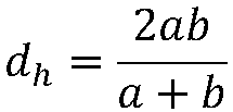
[0025] Pressure drop for parallel channels:

[0026] For laminar flow:

[0027] For turbulent flow:

[002...


PUM


Abstract

The invention discloses a heat dissipation panel with variable-width water channels. The heat dissipation effect of each water channel is balanced through changing the widths of the water channels; the water channel far away from a main inlet and a main outlet is gradually widened; and one or more S-shaped water channel is used at one side near the main inlet and the main outlet. According to theheat dissipation panel with the variable-width water channels, the targets of more uniform temperature distribution and a better heat dissipation effect can be achieved.

Description

technical field [0001] The invention specifically relates to a cooling plate for variable-width water channels. Background technique [0002] Due to its small size and high heat dissipation performance, liquid cooling devices are widely used as cooling devices for high-power electronic equipment. Existing liquid cooling plates, such as the Chinese patent CN105658027A "Liquid cooling plate for cooling electronic components", use a plurality of "S-shaped" serial water channels connected end to end to ensure consistent flow rates, and at the same time add grooves in the water channels to Increase the cooling area. If the liquid flow distance is too long, it will inevitably cause the temperature difference between the inlet and outlet, resulting in uneven heat dissipation or local overheating. At the same time, in a system with a large rated flow rate, the pressure drop of the S-shaped water channel will cause the flow rate to fail to reach the rated flow rate, resulting in ov...

Claims


Application Information

Patent Timeline
IPC IPC(8): H05K7/20
CPCH05K7/20218
Inventor 赵冠李岳
Owner 张家港首驱动力科技有限公司
Why Eureka
Try Eureka