
Atomizers and Electronic Cigarettes

A technology for atomizers and electronic cigarettes, applied in tobacco, smoker's products, applications, etc., can solve problems such as poor conduction of leaking smoke and liquid, and achieve the effects of improving user experience, convenient disassembly, and convenient operation.

Active Publication Date: 2020-06-19
深圳市聚维电子科技有限公司
View PDF7 Cites 0 Cited by
  • Summary
  • Abstract
  • Description
  • Claims
  • Application Information

AI Technical Summary

Problems solved by technology

[0003] Based on this, it is necessary to provide an atomizer and an electronic cigarette to solve at least one of the problems of liquid leakage, dry burning and poor conduction of smoke liquid

Method used


Image

  • Atomizers and Electronic Cigarettes
  • Atomizers and Electronic Cigarettes
  • Atomizers and Electronic Cigarettes

Examples


Embodiment 2

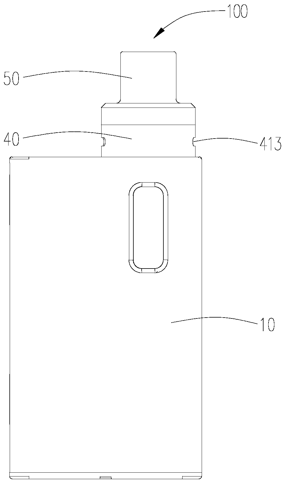
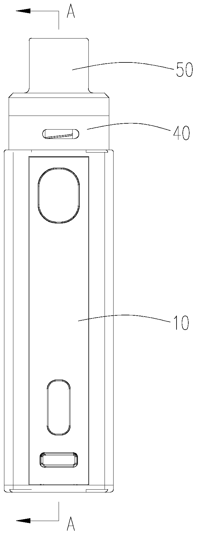
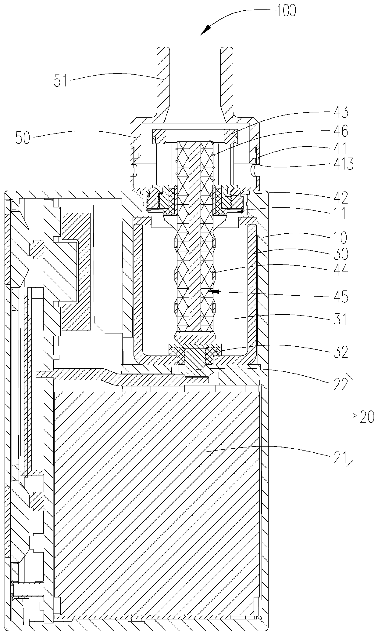
[0067] see Figure 8 , the difference between the electronic cigarette (shown in the figure) provided in the second embodiment and the electronic cigarette 100 in the first embodiment is that only the first liquid suction member 451 can be arranged in the accommodating cavity of the pole 44, and the atomization The cavity 422 includes both the first liquid absorbing member 451 and the second liquid absorbing member 452, that is, a part of the liquid guiding member 45 is accommodated in the accommodating cavity, and the other part of the liquid guiding member 45 is accommodated in the mist. In the atomizing cavity 422, the first liquid absorbing member 451 in the accommodating cavity absorbs the smoke liquid and conducts it upward, and when the smoke liquid reaches the atomizing cavity 422, it passes through the second liquid suction member 451 attached to the first liquid suction member 451. The element 452 reaches the heating element 46 and is heated and atomized. In the sec...


PUM


Abstract

The invention discloses an atomizer. The atomizer comprises a liquid storage part with a liquid storage cavity and an atomizing head with an atomization cavity and installed above the liquid storage part. The liquid storage part has an electrode at the bottom. The atomizing head comprises a drainage part and a pole column which extends into the liquid storage part. The interior of the pole columnis hollow and is electrically connected with the electrode. The lower end of the drainage part is arranged in the pole column and the upper end of the drainage part is arranged in the atomization cavity. A liquid inlet hole connected with the liquid storage cavity is formed in the pole column. The atomizing head avoids a situation of leaking caused when too much tobacco juice enters the atomization cavity, has quick drainage speed, avoids dry burning and therefore improves user experience. In the meantime, by virtue of setting of the pole column and the liquid inlet hole, the drainage part islimited and the drainage rate is accelerated. The invention also discloses an electronic cigarette comprising the atomizer.

Description

technical field [0001] The invention relates to the technical field of simulated smoking, in particular, to an atomizer and an electronic cigarette. Background technique [0002] In the existing electronic cigarette structure, the atomizing head for atomizing the liquid is generally arranged inside the liquid storage cavity or at the lower part of the liquid storage cavity. into the chemical cavity, resulting in liquid leakage. On the other hand, since the liquid guiding member used for liquid guiding is often a fiber rope, the liquid smoke enters into the atomization cavity by osmosis. Therefore, the liquid guiding rate is relatively slow. When the user draws too fast, the heating power is too high. When the liquid conduction efficiency is low, a dry burning phenomenon will occur, thereby reducing the user experience. The liquid guiding rate refers to the distance traveled by the liquid in a unit time during the movement of the liquid from one end of the liquid guiding me...

Claims


Application Information

Patent Timeline
Patent Type & Authority Patents(China)
IPC IPC(8): A24F40/46A24F40/10A24F40/40
CPCA24F47/008
Inventor 不公告发明人
Owner 深圳市聚维电子科技有限公司
Learn More