
Lateral discharging type discharging device of ball mill

A ball mill, side-discharge technology, applied in the field of side-discharge ball mill discharge device, can solve the problems of affecting sealing performance, inconvenient processing, material residue, etc., and achieve the effect of ensuring stability and timeliness, avoiding interference and saving costs

Inactive Publication Date: 2018-10-09
CHANGSHA UNIVERSITY OF SCIENCE AND TECHNOLOGY
View PDF9 Cites 0 Cited by
  • Summary
  • Abstract
  • Description
  • Claims
  • Application Information

AI Technical Summary

Problems solved by technology

[0004] 1. In the process of discharging, if it is used for a long time, there will be materials remaining in the valve plate or valve plug of the discharging device, which will affect the sealing performance and cause stress damage to the structure after long-term use
[0005] 2. There are technical solutions for cleaning the valve plate in the prior art, such as cleaning after disassembly, more advanced ones are cleaning through air blowing holes, such as CN105546126A, but it needs to drill holes on small parts, and due to size limitations, The path of the hole often needs to be bent, which brings great inconvenience to the processing, and it needs to be equipped with a special air pump and connecting pipeline, which is costly
[0006] 3. In the prior art, when sampling the tank body, it is necessary to open holes on the tank body. However, since it is not produced in conjunction with the tank body, special staff are required to install it, and the cost is relatively high.
[0007] 4. The sampling tube of the prior art cannot obtain a stable and continuous sample for a period of time due to the flow of the material
[0008] 5. The switching of the three-way pipeline in the prior art often uses a large ball head, that is, the valve body is larger than the diameter of the pipeline, but it increases the volume of the pipeline and is difficult to adapt to compact working conditions
[0009] 6. In the discharge valve of the prior art, residual material will be generated during the discharge process, and the discharge path cannot be controlled or the cost is high although it is controlled

Method used


Image

  • Lateral discharging type discharging device of ball mill
  • Lateral discharging type discharging device of ball mill
  • Lateral discharging type discharging device of ball mill

Examples


Embodiment Construction

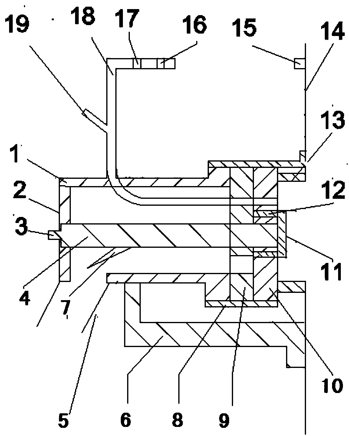
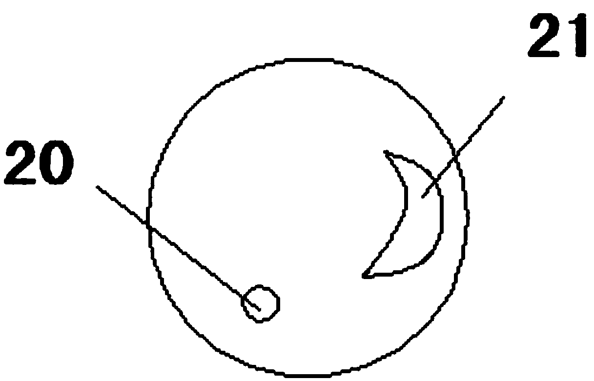
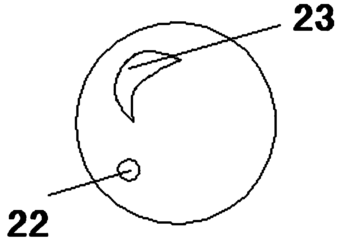
[0034] A discharge device for a side-discharge ball mill, including a valve body, a limit plate, a short column, a valve stem, a discharge pipe, a bracket, a material guide, a segmented screw sleeve, a static valve disc, a movable valve disc, and a limit member , drive column, connectors, ball mill tank, sensor, first stop valve, second stop valve, sampling pipeline, purge pipeline, sampling purge hole 1, discharge hole 1, sampling purge hole 2, exhaust material hole 2, chute, rotating ring, and cut-off ring; the bracket is provided under the valve body, and the right end of the bracket is connected to the tank body of the ball mill; the valve body is arranged on the side of the tank body of the ball mill, and the left end of the valve body is provided The right end of the valve body is provided with a radially extending ring-shaped protrusion, a static valve disc is set on the right side of the protrusion, and a moving valve disc is set on the right side of the static valve di...


PUM


Abstract

The invention discloses a lateral discharging type discharging device of a ball mill. The lateral discharging type discharging device of the ball mill comprises a valve body, a limiting disc, a shortcolumn, a valve rod, a discharge pipe, a support, a material guide part, a segmented thread sleeve, a static valve disc, a movable valve disc, a limiting part, a driving column, a connecting part, a ball mill tank body, a sensor, a first stop valve, a second stop valve, a sampling pipeline, a purging pipeline, a sampling purging hole I, a discharge port I, a sampling purging hole II, a discharge port II, a sliding groove, a rotating ring and a truncated ring, wherein the support is arranged below the valve body, and the right end of the support is connected to the ball mill tank body.

Description

technical field [0001] The invention relates to the related field of ball mills, in particular to a side discharge ball mill discharge device. Background technique [0002] Ball mill is the key equipment for crushing materials after being crushed. It is mainly used in cement, silicate products, new building materials, refractory materials, chemical fertilizers, black and non-ferrous metal beneficiation, glass ceramics and other industries. [0003] In actual use, the existing ball mill has the following problems: [0004] 1. In the process of discharging, if it is used for a long time, there will be materials remaining in the valve plate or valve plug of the discharging device, which will affect the sealing performance, and cause stress damage to the structure after long-term use. [0005] 2. There are technical solutions for cleaning the valve plate in the prior art, such as cleaning after disassembly, more advanced ones are cleaning through air blowing holes, such as CN10...

Claims


Application Information

Patent Timeline
IPC IPC(8): B02C17/18B02C17/10
CPCB02C17/10B02C17/183B02C17/1865
Inventor 张健
Owner CHANGSHA UNIVERSITY OF SCIENCE AND TECHNOLOGY
Learn More