Propeller arm hanging type counter-rotating device, counter-rotating system and ship
A technology of paddle arms and counter-rotating propellers, which is applied in ship propulsion, ship parts, ship construction, etc. It can solve the problems of propeller installation and use of rudder blade restrictions, large counter-rotating propeller thrust of the rudder stock, and limited power, etc., to achieve convenience Development and design of products, promotion of efficiency improvements, and high usability effects
- Summary
- Abstract
- Description
- Claims
- Application Information
AI Technical Summary
Problems solved by technology
Method used
Image
Examples
Embodiment 1
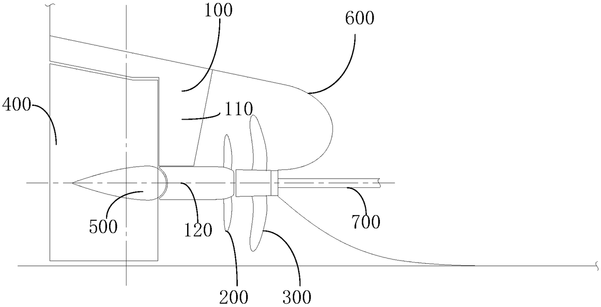
[0035] This embodiment provides a paddle arm 100-type counter-rotating device, including a paddle-hanging arm 100 and a counter-rotating paddle 200;
[0036] The counter-rotating propeller 200 is installed between the propeller 300 and the rudder blade 400 and is set independently;
[0037] The oar hanging arm 100 is respectively connected with the counter-rotating oar 200 and the hull plate 600 , and can drive the counter-rotating oar 200 to adjust the position of the counter-rotating oar 200 .
[0038] The analysis of the technical effects that can be realized by the 100-type counter-rotating device of the paddle arm provided in this embodiment is as follows:
[0039] The paddle arm 100 type counter-rotation device provided by the present invention includes the paddle arm 100 and the counter-rotating paddle 200; the counter-rotating paddle 200 is installed between the propeller 300 and the rudder blade 400 and is set independently; the paddle-hanging arm 100 is respectively ...
Embodiment 2
[0055] This embodiment provides a counter-rotation system including the 100-type counter-rotation device of the paddle-hanging arm mentioned in Embodiment 1, and also includes a rudder blade 400 and a propeller 300, and the 100-type counter-rotation device of the paddle-hanging arm is movably installed on the rudder Between the blade 400 and the propeller 300.
[0056] Among them, the paddle arm 100 type counter-rotation device includes the paddle arm 100 and the counter-rotating paddle 200; the counter-rotating paddle 200 is installed between the propeller 300 and the rudder blade 400 and is set independently; the paddle-hanging arm 100 is connected to the counter-rotating paddle 200 respectively It is connected with the hull plate 600 and can drive the counter-rotating propeller 200 to adjust the position of the counter-rotating propeller 200 . In the working state, the rotation axis of the counter-rotating propeller 200 coincides with the rotation axis of the propeller 300 ...
Embodiment 3
[0060] This embodiment provides a ship, including the contra-rotation system mentioned in Embodiment 2.
[0061] Wherein, the counter-rotating system includes a 100-type counter-rotating device with a paddle-hanging arm, a rudder blade 400 and a propeller 300 , and the 100-type counter-rotating device with a paddle-hanging arm is movably installed between the rudder blade 400 and the propeller 300 . The paddle arm 100 type counter-rotation device includes the paddle arm 100 and the counter-rotating propeller 200; the counter-rotating propeller 200 is installed between the propeller 300 and the rudder blade 400 and is set independently; The plate 600 is connected to drive the counter-rotating paddle 200 to adjust the position of the counter-rotating paddle 200 . In the working state, the rotation axis of the counter-rotating propeller 200 coincides with the rotation axis of the propeller 300 . The contra-rotating propeller 200 is located in the wake field of the propeller 300 ...
PUM
 Abstract
Description
Claims
Application Information
 - R&D
- Intellectual Property
- Life Sciences
- Materials
- Tech Scout
- Unparalleled Data Quality
- Higher Quality Content
- 60% Fewer Hallucinations
Browse by: Latest US Patents, China's latest patents, Technical Efficacy Thesaurus, Application Domain, Technology Topic, Popular Technical Reports.
© 2025 PatSnap. All rights reserved.Legal|Privacy policy|Modern Slavery Act Transparency Statement|Sitemap|About US| Contact US: help@patsnap.com

