Water treatment adjusting device

A technology for adjusting equipment and water treatment, which is applied in water/sewage treatment equipment, water/sewage treatment, water treatment parameter control, etc., and can solve problems such as incomplete filtration of filter elements, inability to automatically adjust water intake, and influence on output water quality, etc. , to achieve the effect of reducing the water inlet pressure, realizing the automatic adjustment of the water inlet, and strengthening the connection strength

Inactive Publication Date: 2018-10-09
浙江兆泉智能科技有限公司
View PDF5 Cites 0 Cited by
  • Summary
  • Abstract
  • Description
  • Claims
  • Application Information

AI Technical Summary

Problems solved by technology

[0005] The embodiment of the present application provides a water treatment adjustment device, which solves the technical problem that the water intake cannot be automatically adjusted in the prior art, and the large water intake may easily lead to incomplete filtration of the filt

Method used


Image

  • Water treatment adjusting device
  • Water treatment adjusting device
  • Water treatment adjusting device

Examples


Embodiment 1

[0035] A water treatment adjustment device, the adjustment device includes:

[0036] an outer casing comprising

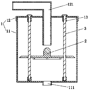
[0037] The housing one 11, the housing one 11 is provided with a accommodating cavity inside, and the opening of the accommodating cavity faces upward; and the bottom of the housing one 11 is provided with a water outlet pipe 111;

[0038] The second shell 12, the second shell 12 is located above the first shell 11, the first shell 11 and the second shell 12 are fixedly connected, and the accommodating cavity inside the first shell 11 is in a sealed state; the second shell The upper part of 12 is provided with a water inlet pipe 121, and the lower part of the water inlet pipe 121 is located in the accommodating cavity;

[0039] Specifically, the material of the outer casing can be made of plastic or metal, depending on the performance parameters of the water treatment equipment; the water outlet pipe 111 is exposed relative to the outer casing, and the outlet pipe...

Embodiment 2

[0057] Embodiment 2, on the basis of Embodiment 1, is further optimized, specifically:

[0058] The adjusting device further includes a magnetic force assembly 4, the magnetic force assembly 4 includes a magnetic force piece 41 and a magnetic force piece 2 42, the magnetic force piece 2 42 is located above the magnetic force piece 41, and the magnetic force between the first magnetic force piece 41 and the second magnetic force piece 42 Attraction, the first magnetic piece 41 and the second 42 are located on the movement track of the adjusting assembly 2; .

[0059] Specifically, at least one of the first magnetic pieces 41 and the second 42 is a magnet, the first magnetic piece 41 is located near the upper surface of the hole 221 of the buoyancy plate 22, and the second magnetic piece 42 is located on the guide post 3, and the magnetic force The second piece 42 is located above the first magnetic piece 41 .

Embodiment 3

[0060] Embodiment 3, on the basis of Embodiment 1 or 2, is further optimized, specifically:

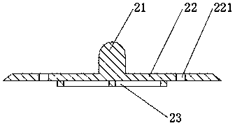
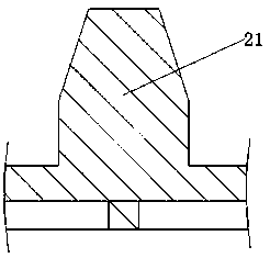
[0061] The inside of the plug 21 is provided with a shunt cavity 211; the inlet end of the shunt cavity 211 is located on the upper surface of the plug 21, and the outlet end is located on the side surface of the groove of the plug 21; the shunt cavity 211 is a curved shape , and the position of the bend of the shunt chamber 211 is lower than the position of the outlet end.

[0062] The shunt chamber 211 is provided with a plurality of outlet ends, and the plurality of outlet ends are arranged symmetrically with respect to the plug 21 .

[0063] Specifically, the shunt cavity 211 is made when the plug 21 is poured, or it can be processed later. The diameter of the inlet port of the shunt cavity 211 is greater than or equal to the diameter of the outlet end, and the diameter of the inlet end is smaller than or equal to the inlet pipe 121. one-third of the diameter.

[0064] Specifica...


PUM


Abstract

The embodiment of the invention provides a water treatment adjusting device, which belongs to the technical field of water treatment filtering equipment. The adjusting device comprises an outer shelland an adjusting assembly, wherein the outer shell comprises a shell I and a shell II, and an accommodating cavity is formed in the shell I and is provided with an upward opening; a water outlet pipeis arranged at the bottom of the shell I; the shell I and the shell II are fixedly connected with each other; a water inlet pipe is arranged the upper part of the shell II, and the lower part of the water inlet pipe is located in the accommodating cavity; the adjusting assembly is located in the accommodating cavity and just below the lower portion of the water inlet pipe, and comprises a buoyancyplate, a plug and a plurality of guide posts which are symmetrically arranged relative to the adjusting assembly, and the adjusting assembly sleeves the guide posts. The water treatment adjusting device achieves the technical effect of reducing the water pressure of inlet water and realizing the automatic adjustment of water inflow.

Description

technical field [0001] The invention relates to the technical field of water treatment and filtration equipment, in particular to a water treatment adjustment device. Background technique [0002] In the domestic or commercial water treatment equipment in the prior art, the raw water is filtered gradually and in a targeted manner mainly by means of filter components in each link, so that the water quality produced by the water treatment meets the standard. [0003] The difference in the effluent quality of the existing water treatment equipment is mainly reflected in the composition and structure of the filter element, followed by the relationship between the water treatment capacity of the filter element per unit time and the water intake per unit time. However, the water treatment equipment is sold nationwide. Due to the difference in the water pressure of the pipe network in different places, the water intake per unit time is different. [0004] Therefore, the technical ...

Claims


Application Information

Patent Timeline
IPC IPC(8): C02F1/00
CPCC02F1/001C02F1/006C02F2201/002C02F2209/40
Inventor 王晓春
Owner 浙江兆泉智能科技有限公司
Why Eureka
Try Eureka