Synchronous recycling and purifying method for oil in oily sludge

A technology of oil and sludge, which is applied in the field of synchronous recovery and purification of oil in oily sludge, can solve the problems of poor treatment effect, high energy consumption, and high treatment cost of high-viscosity oily sludge, and achieve good oil-water separation and contact area The effect of increasing, increasing liquidity

Pending Publication Date: 2018-10-09
RES CENT FOR ECO ENVIRONMENTAL SCI THE CHINESE ACAD OF SCI
View PDF12 Cites 4 Cited by
  • Summary
  • Abstract
  • Description
  • Claims
  • Application Information

AI Technical Summary

Problems solved by technology

[0004] Aiming at the disadvantages of poor treatment effect, high treatment cost and high energy consumption of high-viscosity oily sludge in heavy oil production areas, the present invention provides a method for synchronously recovering and purifying oil in sludge by using steam jetting, which is harmless for harmful sludge, Provide support for resource utilization

Method used


Image

  • Synchronous recycling and purifying method for oil in oily sludge

Examples


Embodiment 1

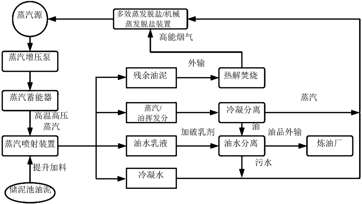
[0023] according to figure 1 The process uses high-viscosity oily sludge as raw material, uses a grab crane to dig up the sludge and transports it to the screw feeder, and the screw feeder transports it to the steam injection box with a feeding rate of 0.5 tons / hour. After the steam is heated and pressure adjusted, the temperature reaches 300°C, the pressure reaches 8MPa, and the steam injection rate is 3 tons / hour. The temperature inside the steam injection box reached 97°C within 20 seconds. Control the residence time of the floating oil layer to be 5 minutes. The oil scraper scrapes off the floating oil layer, and then performs demulsification and cyclone dehydration. The application amount of the thick oil demulsifier is 2g / L. In this embodiment, the oil recovery rate is 0.22 tons / hour, and the sludge residue discharge rate is 0.25 tons / hour. The total metal impurity content of recovered oil was reduced by 82%, among which Fe and Zn were reduced by 41% and 17% respectiv...

Embodiment 2

[0025] according to figure 1 The process uses high-viscosity oily sludge as raw material, uses a grab crane to dig up the sludge and transports it to the screw feeder, and the screw feeder transports it to the steam injection box, and the feeding rate is 1 ton / hour. After the steam is heated and pressure adjusted, the temperature reaches 350°C, the pressure reaches 16MPa, and the steam injection rate is 6 tons / hour. The temperature inside the steam injection box reaches 98°C within 15 seconds. Control the residence time of the floating oil layer to be 3 minutes. The oil scraper scrapes off the floating oil layer, and then performs demulsification and cyclone dehydration. The application amount of the thick oil demulsifier is 2g / L. In this embodiment, the oil recovery rate is 0.46 tons / hour, and the sludge residue discharge rate is 0.5 tons / hour. The total metal impurity content of recovered oil is reduced by 78%, among which Fe and Zn are reduced by 26% and 17% respectively...


PUM


Abstract

The invention relates to a synchronous recycling and purifying method for oil in oily sludge. The synchronous recycling and purifying method specifically comprises a feeding system, a steam preparation system, a spraying system, an oil water separation system, a condensation separation system, a condensate water desalting and reinjecting system, and an oily sludge residue combustion system. The synchronous recycling and purifying method is characterized in that the high temperature and the strong-impact dispersion effect of the sprayed steam are used to recycle and purify the oil sludge, the recycled oil is dehydrated and conveyed to an oil refinery, the condensate water is desalted and reinjected to generate steam, and the oily sludge residue is combusted to recycle the heat energy. The various systems of the method are linked with one another and are efficient, fast, clean and environmentally friendly; a used steam spraying device is simple in structure and can run continuously.

Description

technical field [0001] The invention relates to a harmless treatment of oily sludge and a method for recovering oil products, which belongs to the new technology of oilfield solid waste treatment in the fields of environmental protection and resource comprehensive utilization, and is especially suitable for the treatment of high-viscosity oil sludge in crude oil storage, transportation and refining industries deal with. Background technique [0002] Oily sludge is a solid and semi-solid waste from the petroleum and petrochemical industries. The annual output in my country is as high as millions of tons, and the stock is huge. Oil sludge contains high concentrations of petroleum hydrocarbons, heavy metals and other toxic components that are difficult to degrade, and is accompanied by stench. If it is not treated in time, it will seriously endanger the ecological environment and the health of humans, animals and plants. Sludge is included in the "National Hazardous Waste List...

Claims


Application Information

Patent Timeline
Patent Type & Authority Applications(China)
IPC IPC(8): C10G1/00
CPCC10G1/002C10G2300/1003
Inventor 张付申夏冬
Owner RES CENT FOR ECO ENVIRONMENTAL SCI THE CHINESE ACAD OF SCI
Why Eureka
Try Eureka