
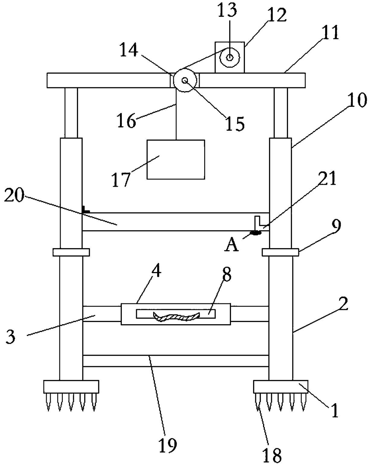
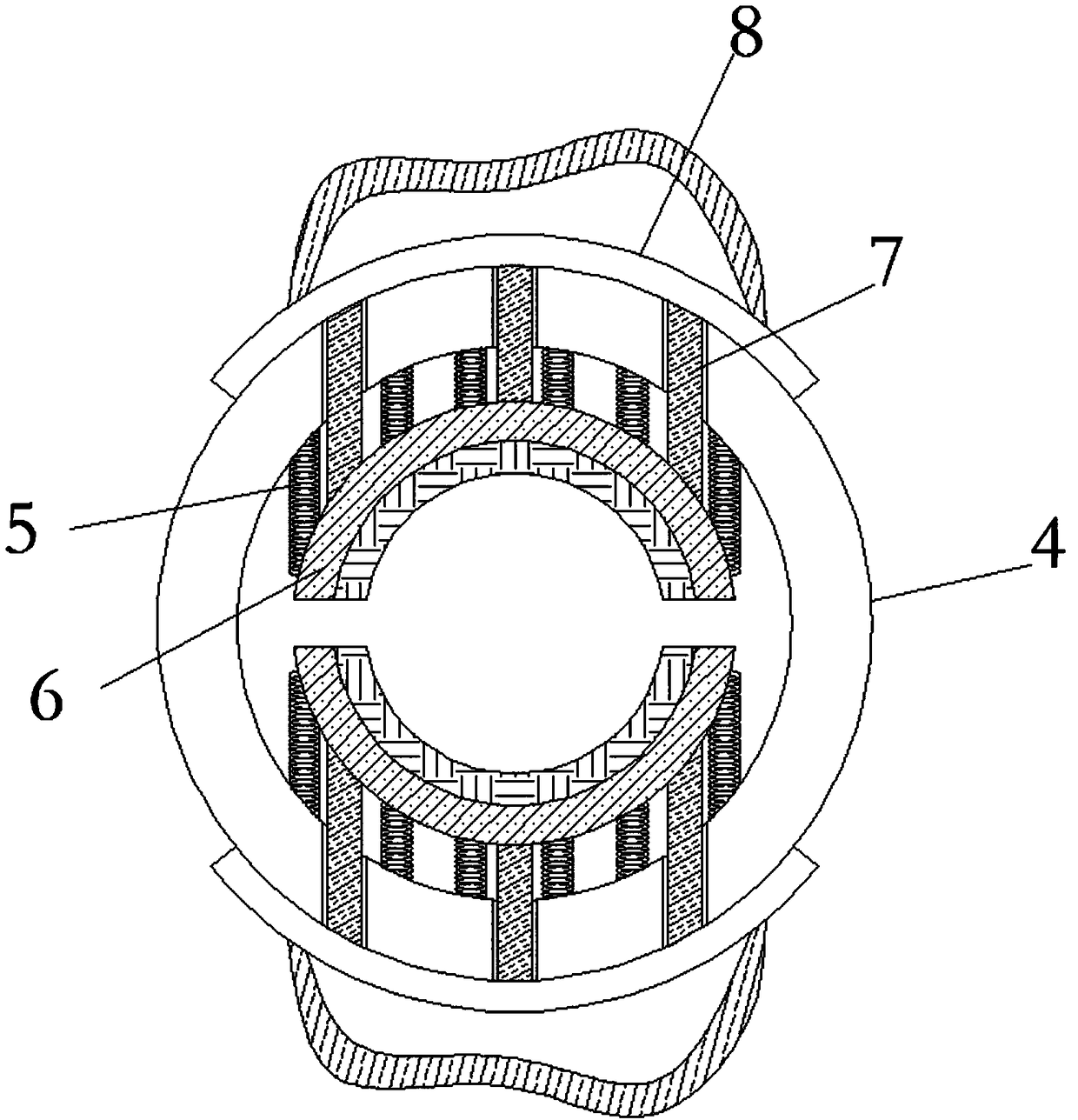
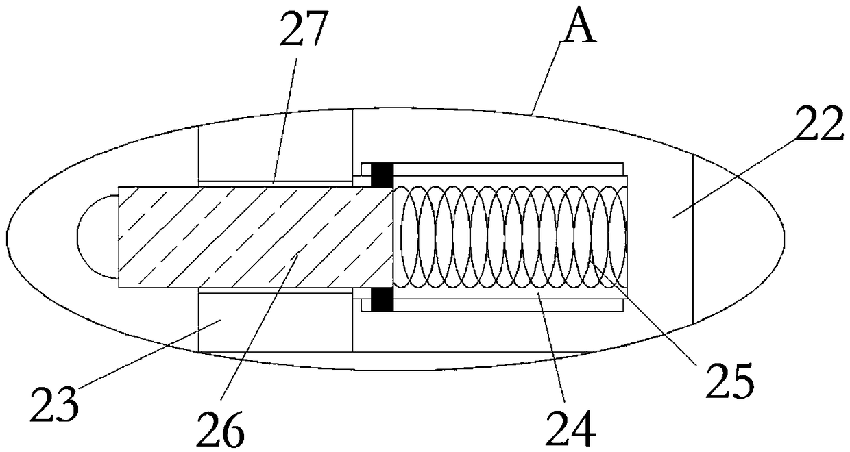
Building piling machine

A pile driver and construction technology, applied in construction, sheet pile walls, foundation structure engineering, etc., can solve the problems of inconvenient piling, achieve labor saving, improve labor efficiency, and have a wide range of applications

Inactive Publication Date: 2018-10-09
CHINA MCC17 GRP
View PDF8 Cites 10 Cited by
  • Summary
  • Abstract
  • Description
  • Claims
  • Application Information

AI Technical Summary

Problems solved by technology

[0004] The purpose of the present invention is to solve the need in the prior art to align the pile body to the position to be driven in. One person supports the pile body, and the other person uses a heavy object to drive the pile body into the soil. This method requires two people to operate , it is very inconvenient when driving piles, and a construction pile driver is proposed

Method used


Image

  • Building piling machine
  • Building piling machine
  • Building piling machine

Examples


Embodiment Construction

[0023] The following will clearly and completely describe the technical solutions in the embodiments of the present invention with reference to the accompanying drawings in the embodiments of the present invention. Obviously, the described embodiments are only some, not all, embodiments of the present invention.

[0024] In describing the present invention, it should be understood that the terms "upper", "lower", "front", "rear", "left", "right", "top", "bottom", "inner", " The orientation or positional relationship indicated by "outside", etc. is based on the orientation or positional relationship shown in the drawings, and is only for the convenience of describing the present invention and simplifying the description, rather than indicating or implying that the referred device or element must have a specific orientation, so as to Specific orientation configurations and operations, therefore, are not to be construed as limitations on the invention.

[0025] refer to Figure ...


PUM


Abstract

The invention discloses a building piling machine. The building piling machine comprises two first support plates. The upper ends of the two first support plates are each provided with two support rods, wherein every two support rods are symmetrical in the front-back direction and are fixedly connected. A same annular frame is fixedly connected among the four support rods through connecting rods.Two symmetrical arc-shaped clamping plates are fixedly connected to the inner side of the annular frame through multiple springs. Multiple limiting rods are fixedly and uniformly connected to the side, close to the annular frame, of each arc-shaped clamping plate. The multiple limiting rods at each side penetrate the surface of the annular frame through through holes formed in the surface of the annular frame and are fixedly connected with the corresponding arc-shaped clamping plate. According to the building piling machine, a pile is hammered into the ground through the impact force generatedby the gravity of a pile hammer; labor force is saved; a pile body does not need to be held by hands, and piling can be achieved; labor efficiency is improved; and in addition, the problem that accidents are caused in the piling process that the pile body is held manually, so that people are injured is avoided.

Description

technical field [0001] The invention relates to the technical field of construction equipment, in particular to a construction pile driver. Background technique [0002] The pile driver is composed of pile hammer, pile frame and auxiliary equipment. The pile hammer is attached between two parallel vertical guide rods (commonly known as gantry) at the front of the pile frame, and is hoisted with a lifting hook. The pile frame is a steel structure tower frame, and a hoist is arranged at the rear of it to lift the pile and the pile hammer. There is a guide frame composed of two guide rods in front of the pile frame, which is used to control the direction of pile driving, so that the pile can accurately penetrate into the ground according to the designed orientation. The basic technical parameters of the pile driver are the impact part weight, impact kinetic energy and impact frequency. Pile hammers can be divided into drop hammers, steam hammers, diesel hammers, hydraulic ha...

Claims


Application Information

Patent Timeline
IPC IPC(8): E02D7/08E02D7/16
CPCE02D7/08E02D7/16
Inventor 王春生柳荣芳杨巧利
Owner CHINA MCC17 GRP
Learn More