Fuel tank system
A fuel tank, fuel technology, applied in the charging system, fuel injection device, fuel injection control and other directions, can solve problems such as fuel overflow
- Summary
- Abstract
- Description
- Claims
- Application Information
AI Technical Summary
Problems solved by technology
Method used
Image

Examples
no. 1 example
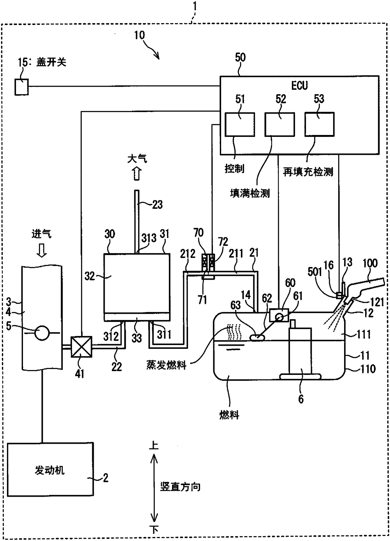
[0017] exist figure 1 A fuel tank system according to a first embodiment is shown in . A fuel tank system 10 according to the first embodiment is provided in a vehicle 1 equipped with an engine 2 which is a gasoline internal combustion engine. The vehicle 1 includes an intake pipe 3 and a fuel tank 11 in addition to the engine 2 and the fuel tank system 10 . Engine 2 generates driving force for driving vehicle 1 . Gasoline is supplied to the engine 2 as fuel to drive the vehicle 1 .
[0018] The intake pipe 3 is connected to the engine 2 . The intake passage 4 is formed inside the intake pipe 3 . One end of the intake passage 4 is connected to a combustion chamber of the engine 2 and the other end of the intake passage 4 is opened to the atmosphere. The intake passage 4 introduces atmospheric air into the combustion chambers of the engine 2 . Air (also referred to as intake air) entering the combustion chamber through intake passage 4 is mixed with fuel injected, for exa...
no. 2 example
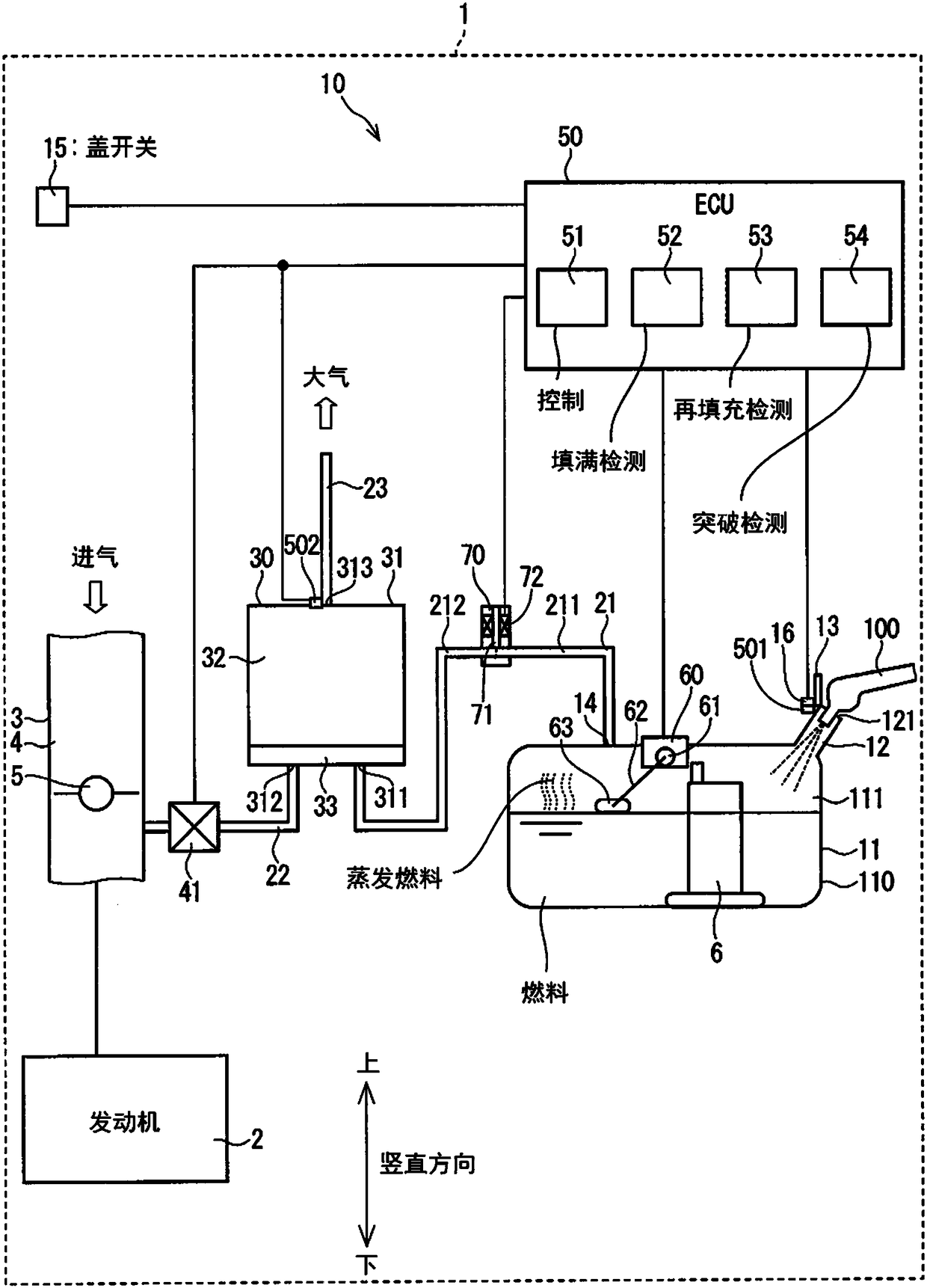
[0051] figure 2 A fuel tank system according to a second embodiment is shown in . In the second embodiment, a concentration sensor 502 is additionally provided. Furthermore, the ECU 50 additionally includes a breakthrough prediction unit 54 .
[0052] The concentration sensor 502 is provided in the tank 30 . The concentration sensor 502 detects the concentration of evaporated fuel in the tank 30 and outputs a signal indicative of the detected concentration to the breakthrough detection section 54 of the ECU 50 . The breakthrough detection unit 54 detects the breakthrough of the tank 30 or predicts the breakthrough time of the tank 30 based on the signal received from the concentration sensor 502 . Breakthrough of the canister 30 means that the vaporized fuel adsorbed by the canister 30 reaches the maximum value of vaporized fuel adsorption of the canister 30 .
[0053] When the breakthrough detection part 54 detects a breakthrough of the tank 30 or predicts a breakthrough...
no. 3 example
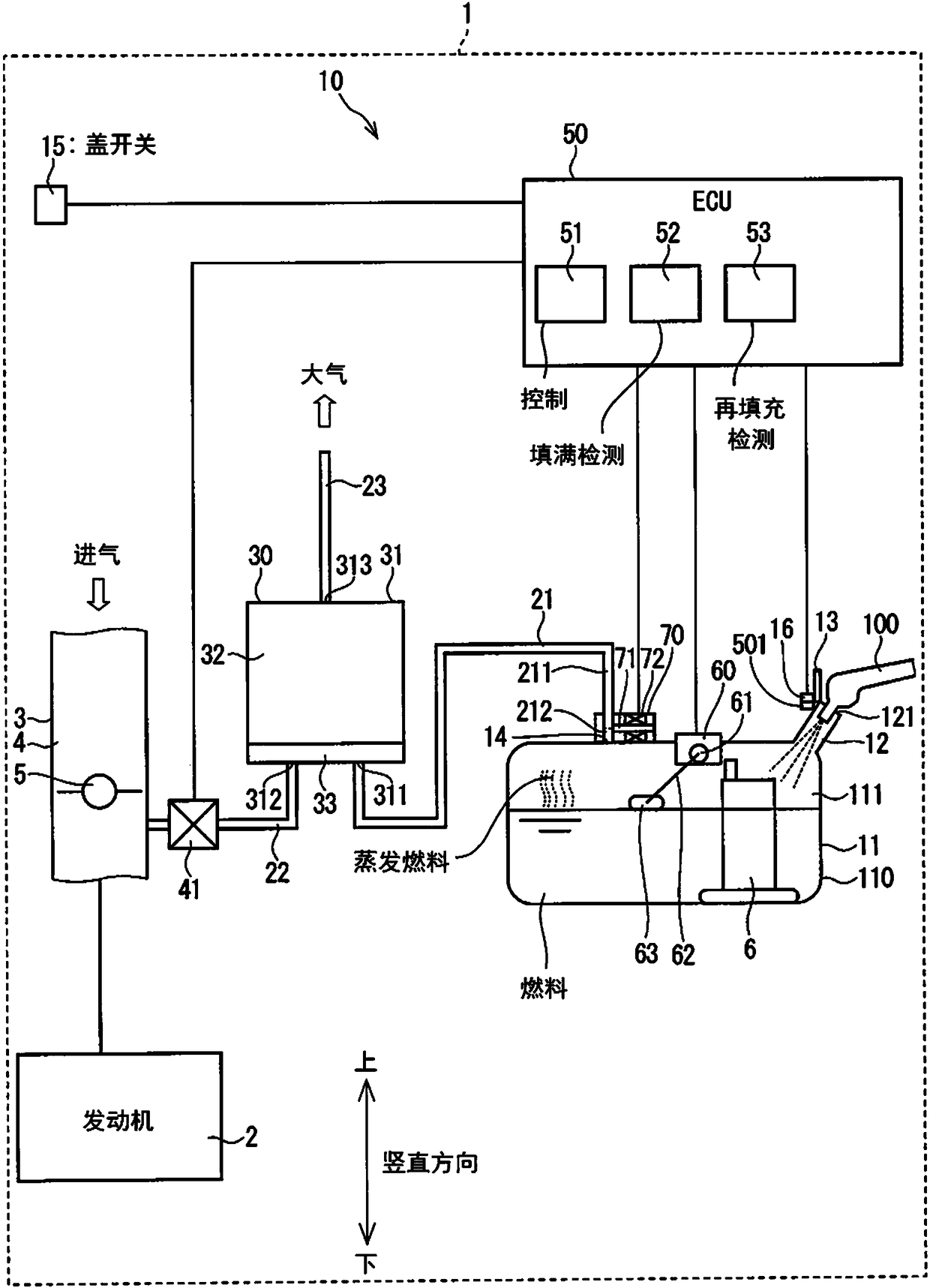
[0058] image 3A fuel tank system according to a third embodiment is shown in . In the third embodiment, the electric control valve 70 is located at a different position from that of the first embodiment. In the third embodiment, the electric control valve 70 is provided at the end of the tank passage 21 on the side of the fuel tank 11 . The electric control valve 70 is attached in contact with the outer wall of the tank body 110 of the fuel tank 11 . The volume of the tank side channel 211 of the tank channel 21 is small compared with the first embodiment. In addition to the configuration and operation of the first embodiment, the third embodiment has the additional configuration and operation described above.
[0059] In the third embodiment, the electric control valve 70 is provided at the end of the tank passage 21 on the side of the fuel tank 11 . As a result, the volume of the tank-side channel 211 of the tank channel 21 is reduced. When fuel is continuously refille...
PUM
 Abstract
Description
Claims
Application Information
 - R&D
- Intellectual Property
- Life Sciences
- Materials
- Tech Scout
- Unparalleled Data Quality
- Higher Quality Content
- 60% Fewer Hallucinations
Browse by: Latest US Patents, China's latest patents, Technical Efficacy Thesaurus, Application Domain, Technology Topic, Popular Technical Reports.
© 2025 PatSnap. All rights reserved.Legal|Privacy policy|Modern Slavery Act Transparency Statement|Sitemap|About US| Contact US: help@patsnap.com