
Combined cable structure

A cable structure and combined technology, applied in the field of combined cable structure, can solve the problems of poor heat dissipation performance, reduced cable service life, increased area usage, etc., to increase shear resistance, increase heat dissipation effect, and increase heat dissipation performance. Effect

Inactive Publication Date: 2018-10-09
吕舒宏
View PDF2 Cites 11 Cited by
  • Summary
  • Abstract
  • Description
  • Claims
  • Application Information

AI Technical Summary

Problems solved by technology

[0002] The buried cable structure in the prior art, after it is buried in the ground, will often be sheared and squeezed, resulting in a reduction in the service life of the cable. The traditional cable structure is only protected by the outer layer, so it is resistant to shearing. The ability to cut and squeeze is poor, the cable core is inconvenient to disassemble, and it is troublesome to recycle later;
[0003] And because the cable is buried underground, its heat dissipation performance is poor. When the cable is used for a long time or in a high temperature environment, its heat dissipation performance is required to be high, otherwise it will affect the normal transmission of the cable.
[0004] In addition, we will also bury a lot of buried water pipes in the ground. These pipes are directly exposed to the outside and are easily damaged by shearing. In the same area, both cables and water pipes must be installed, which will undoubtedly increase The area of ​​the area used

Method used


Image

  • Combined cable structure
  • Combined cable structure

Examples


Embodiment Construction

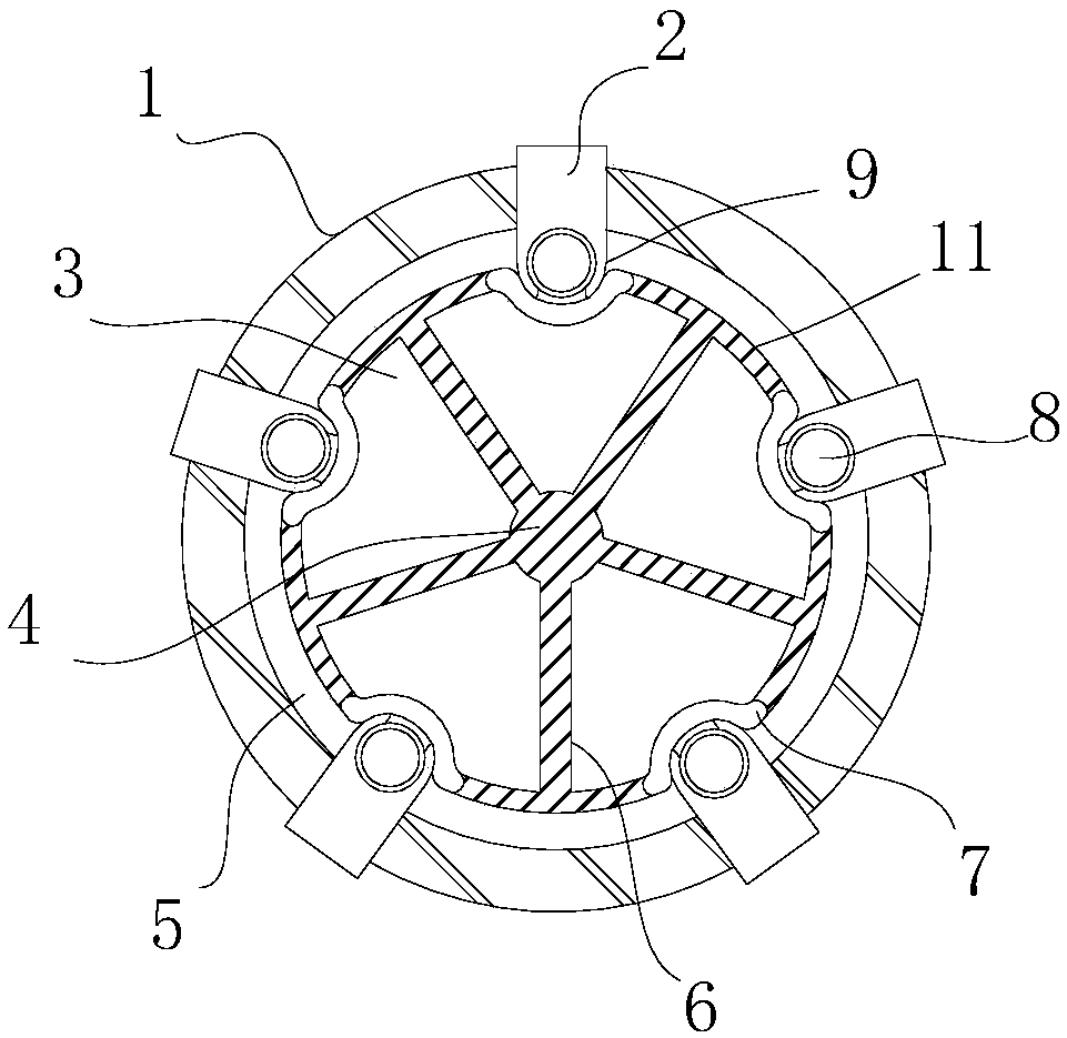
[0022] Such as figure 1 As shown, the combined cable structure includes a cable sheath layer 1, an installation cavity 5 is formed in the middle of the cable sheath layer 1, and more than one fixing clip is clamped on the outside of the cable sheath layer 1, and the fixing clips are evenly distributed and clamped. On the outside of the cable jacket layer 1, the inner end of the fixing clip extends into the installation cavity 5, and a cable core 8 is installed on the inner end of the fixing clip, and the outside of the cable core 8 is wrapped with an independent protective layer;

[0023] In the middle installation cavity of the cable jacket layer 1, a water delivery pipe 11 is installed for positioning and supporting by each fixing clip. An elastic rubber layer 7 is arranged on the water delivery pipe 11 facing the cable core, and one end of the fixing clip Extruded into the elastic rubber layer.

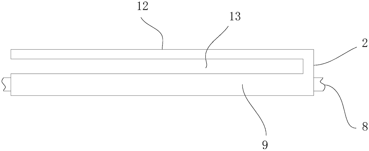
[0024] Such as figure 2 As shown, the fixing clip includes a metal protecti...


PUM


Abstract

The invention discloses a combined cable structure, which comprises a cable outer layer, wherein a mounting cavity is formed in the middle of the cable outer layer; more than one fixing clip is clamped on the outer portion of the cable outer layer, and the fixing clips are uniformly distributed and clamped outside the cable outer layer; the inner end of the fixing clip protrudes into the mountingcavity, and the inner end of the fixing clip is provided with a cable core; the outer part of the cable core is wrapped with a separate protective layer; a water pipe is mounted in the mounting cavityin the middle of the cable outer layer and fixed and supported through the fixing clips; an elastic rubber layer is arranged at a position on the water pipe aligned to the cable core; and one end ofthe fixing clip is extruded and arranged to the elastic rubber layer. The combined cable structure has simple structure, great ventilation and heat dissipation performance and excellent shearing resistance; the cable core is easy to assemble and disassemble; the water pipe is arranged in the middle so as to combine the cable and the water pipe, thereby saving the layout area; and the water pipe isused for cooling the cable core, thereby increasing the heat dissipation performance.

Description

technical field [0001] The invention relates to a cable, in particular to a combined cable structure. Background technique [0002] The buried cable structure in the prior art, after it is buried in the ground, will often be sheared and squeezed, resulting in a reduction in the service life of the cable. The traditional cable structure is only protected by the outer layer, so it is resistant to shearing. The ability to cut and squeeze is poor, the cable core is inconvenient to disassemble, and it is troublesome to recycle later; [0003] And because the cable is buried underground, its heat dissipation performance is poor. When the cable is used for a long time or in a high temperature environment, its heat dissipation performance is required to be high, otherwise it will affect the normal transmission of the cable. [0004] In addition, we will also bury a lot of buried water pipes in the ground. These pipes are directly exposed to the outside and are easily damaged by she...

Claims


Application Information

Patent Timeline
IPC IPC(8): H01B7/42H01B7/40H01B7/18
CPCH01B7/423H01B7/1805H01B7/1815H01B7/185H01B7/40H01B7/426H01B7/428
Inventor 吕舒宏
Owner 吕舒宏
Learn More