Dual-band corner reflector and design method thereof

A corner reflector and dual-band technology, applied in the field of radar, can solve the problem that the corner reflector cannot meet the engineering application requirements with similar scattering characteristics

Active Publication Date: 2018-10-09
BEIJING INST OF ENVIRONMENTAL FEATURES +1
View PDF6 Cites 5 Cited by
  • Summary
  • Abstract
  • Description
  • Claims
  • Application Information

AI Technical Summary

Problems solved by technology

[0004] The technical problem to be solved by the present invention is that traditional corner reflectors cannot meet the requirements of engineering applications with similar scattering characteristics in dual frequency bands. Aiming at the defects in the prior art, a dual frequency band corner reflector is provided, which can realize dual frequency band corner reflection The scattering characteristics of the detector are similar in different frequency bands

Method used


Image

  • Dual-band corner reflector and design method thereof
  • Dual-band corner reflector and design method thereof
  • Dual-band corner reflector and design method thereof

Examples


Embodiment 1

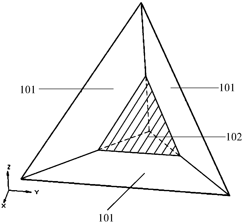
[0031] Such as figure 1 As shown, a dual-band corner reflector provided by an embodiment of the present invention includes: three metal plates 101 and a frequency selective surface dielectric plate 102;

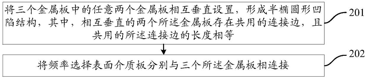
[0032] Any two of the three metal plates 101 are arranged perpendicular to each other to form a semi-elliptical concave structure, wherein the two metal plates perpendicular to each other have a common connecting edge, and the shared The lengths of the connected sides are equal;

[0033] The frequency selective surface dielectric plate 102 is respectively connected to the three metal plates.

[0034] In the embodiment of the present invention, the rigid structure formed by the arrangement of three metal plates perpendicular to each other can not only avoid displacement and strain of the dual-band corner reflector under the action of coincidence when the dual-band corner reflector is subjected to a strong impact, It can also minimize the attenuation of the RCS level, and con...

Embodiment 2

[0037] In an embodiment of the present invention, the shape of the frequency selective surface dielectric plate includes an equilateral triangle.

[0038] In the embodiment of the present invention, the shape of the frequency selective surface dielectric plate may be any polygon, for example, an isosceles right triangle, a square, a pentagon, or a rectangle. However, in order to better control the transmittance of electromagnetic waves at different frequencies, the optimum shape of the frequency selective surface dielectric plate is an equilateral triangle.

Embodiment 3

[0040] In an embodiment of the present invention, the distance from the intersection of the vertex of the frequency selective surface dielectric plate in the shape of an equilateral triangle and the shared connecting side to the intersection of the three metal plates, and the shared The ratio of the lengths of the connecting sides is a predetermined frequency selective surface dielectric plate size ratio factor.

[0041] In the embodiment of the present invention, when the shape of the frequency selective surface dielectric plate is an equilateral triangle, the three vertices of the frequency selective surface dielectric plate and the three shared connecting sides form three one-to-one corresponding intersection points, and the three intersection points to three The distance between the intersection points of two mutually perpendicular metal plates is equal.

[0042] It can be understood that the size ratio factor of the frequency selective surface dielectric plate determines ...


PUM


Abstract

The invention provides a dual-band corner reflector and a design method thereof. The dual-band corner reflector comprises three metal plates and a frequency selective surface dielectric plate; whereinany two of the three metal plates are perpendicular to each other, so as to form a semi-ellipse-shaped sunken structure, the two metal plates which are perpendicular to each other share a connectionedge, and all the shared connection edges are equal in length; and the frequency selective surface dielectric plate is connected with the three metal plates. Through adoption of the dual-band corner reflector of the invention, scattering properties of the dual-band corner reflector at different frequency bands can be similar.

Description

technical field [0001] The invention relates to the technical field of radar, in particular to a dual-band corner reflector and a design method thereof. Background technique [0002] At present, there is a practical engineering requirement that the scattering characteristics of the same corner reflector should be similar under two frequency bands with large differences. However, the scattering characteristics of traditional corner reflectors are proportional to the square of the radar frequency. It can be seen that the magnitude of the radar cross section (Radar Cross Section, RCS) of the same corner reflector is different in different frequency bands. When the frequency is doubled, the RCS level of the same corner reflector can be increased by 6dB, and when the frequency is tripled, the RCS level of the same corner reflector can be increased by 10dB, which cannot adapt to the current stage of corner reflection The engineering application requirements of the device having s...

Claims


Application Information

Patent Timeline
IPC IPC(8): H01Q15/18H01Q15/14H01Q15/00
CPCH01Q15/0013H01Q15/141H01Q15/18
Inventor 崔闪李胜闫华车永星汪浩崔宏林丛滨何四华
Owner BEIJING INST OF ENVIRONMENTAL FEATURES
Why Eureka
Try Eureka