Eureka AIR delivers breakthrough ideas for toughest innovation challenges, trusted by R&D personnel around the world.

Electronic circuit board welding mechanism

A technology for electronic circuit boards and welding mechanisms, applied in welding equipment, auxiliary devices, metal processing, etc., can solve the problems of troublesome cleaning of circuit boards, cumbersome operations, large inclusions, etc., and achieve the effect of preventing direct settlement on the circuit board

Active Publication Date: 2018-10-12
赣州联宇宏科技有限公司
View PDF8 Cites 1 Cited by
  • Summary
  • Abstract
  • Description
  • Claims
  • Application Information

AI Technical Summary

Problems solved by technology

[0003] The existing electronic circuit board welding mechanism uses bolts to lock and push the movable support plate, and cooperates with the static support plate to hold and press circuit boards of different lengths and specifications, so that when the welding mechanism welds electronic components on the circuit board , to keep the circuit board stable, but the operation is cumbersome. At the same time, during the welding process, the welding fume is often mixed with a large amount of dust. Once the dust settles on the circuit board, it will bring some trouble to the circuit board cleaning after welding.

Method used


Image

  • Electronic circuit board welding mechanism
  • Electronic circuit board welding mechanism
  • Electronic circuit board welding mechanism

Examples


Embodiment Construction

[0023] The following will clearly and completely describe the technical solutions in the embodiments of the present invention with reference to the accompanying drawings in the embodiments of the present invention. Obviously, the described embodiments are only some, not all, embodiments of the present invention. Based on the embodiments of the present invention, all other embodiments obtained by persons of ordinary skill in the art without making creative efforts belong to the protection scope of the present invention.

[0024] In describing the present invention, it should be understood that the terms "longitudinal", "transverse", "upper", "lower", "front", "rear", "left", "right", "vertical", The orientations or positional relationships indicated by "horizontal", "top", "bottom", "inner", "outer", etc. are based on the orientations or positional relationships shown in the drawings, and are only for the convenience of describing the present invention, rather than indicating or...


PUM


Abstract

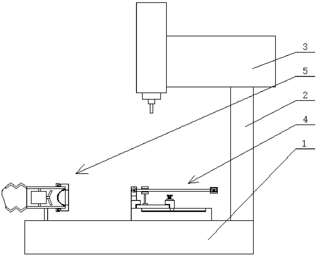
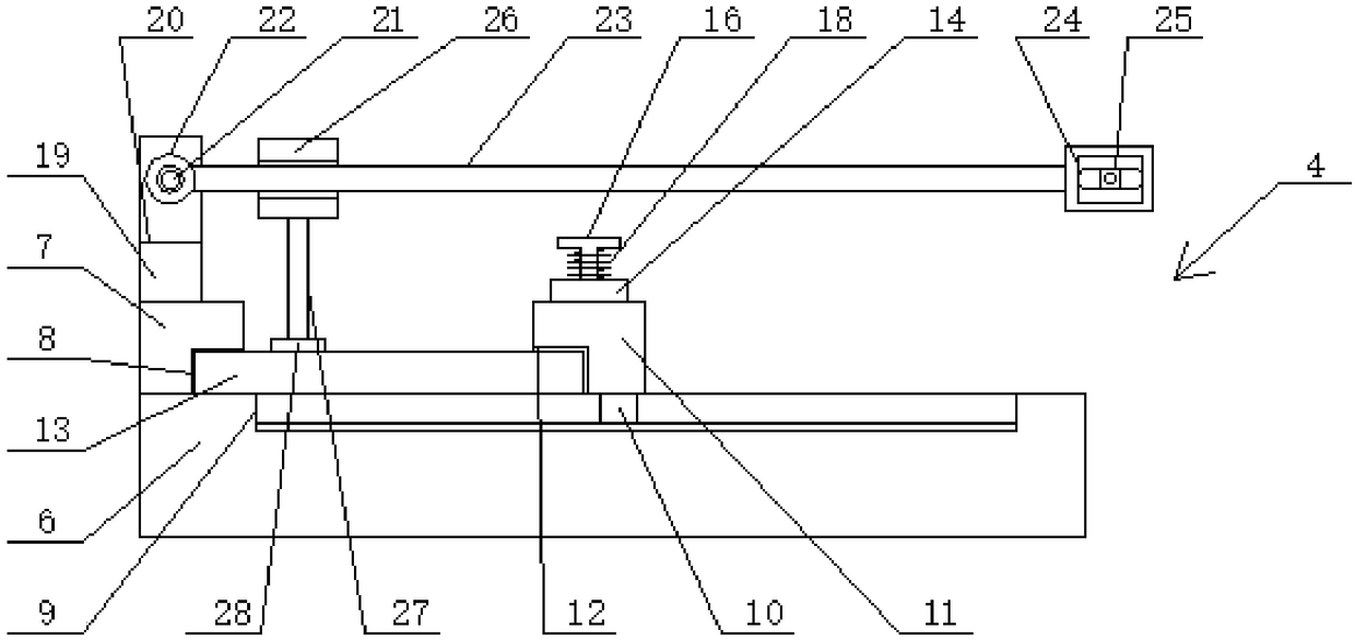
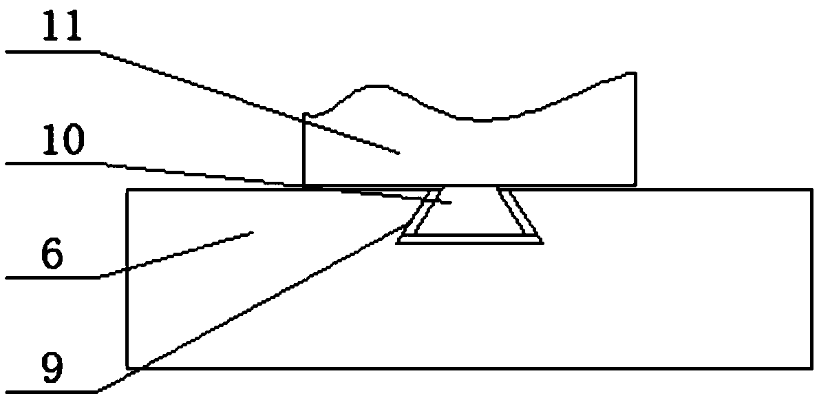
The invention discloses an electronic circuit board welding mechanism. The electronic circuit board welding mechanism comprises a worktable; the right side of the upper end of the worktable is fixedlyconnected with a support column; a welding machine body is fixedly mounted at the upper end of the support column; a circuit board fixing device is fixedly mounted on the right side of the upper endof the worktable; and a smoke discharge device is fixedly mounted on the left side of the upper end of the worktable. A bolt is pulled out from a slot; a second square butting plate moves to the rightside; circuit boards with different length model numbers are inserted in a first square butting plate and the second square butting plate; the second square butting plate moves to the left side; thefirst square butting plate and the second square butting plate butt against the circuit boards; the bolt is inserted in the slot to conveniently fix the circuit boards with different length model numbers; and in a state of blades of an exhaust fan rotated to the right side for air suction, through filtration by a pan type leakage net and a nylon cloth layer, large and small welding smoke particlesare filtered on the right sides thereof, so that the welding smoke particles are prevented from directly precipitating on the circuit boards.

Description

technical field [0001] The invention relates to the technical field of circuit board welding, in particular to an electronic circuit board welding mechanism. Background technique [0002] The circuit board is a highly reliable and excellent flexible printed circuit board made of polyimide or polyester film, which is used in various fields. [0003] The existing electronic circuit board welding mechanism uses bolts to lock and push the movable support plate, and cooperates with the static support plate to hold and press circuit boards of different lengths and specifications, so that when the welding mechanism welds electronic components on the circuit board, , to keep the circuit board stable, but the operation is cumbersome. At the same time, during the welding process, the welding fume is often mixed with a large amount of dust. Once the dust settles on the circuit board, it will bring certain troubles to the cleaning of the circuit board after welding. Contents of the in...

Claims


Application Information

Patent Timeline
Patent Type & Authority Applications(China)
IPC IPC(8): B23K3/00B23K3/08
CPCB23K3/00B23K3/08B23K3/087
Inventor 唐庆联
Owner 赣州联宇宏科技有限公司
Why Eureka
Eureka Blog
Learn More