Intelligent control type building facility

A construction equipment and intelligent control technology, applied to other manufacturing equipment/tools, manufacturing tools, etc., can solve the problems of low safety, complex structure, single function, etc., and achieve the effect of convenient operation and simple structure

Inactive Publication Date: 2018-10-12
戎佰腾
View PDF0 Cites 6 Cited by
  • Summary
  • Abstract
  • Description
  • Claims
  • Application Information

AI Technical Summary

Problems solved by technology

[0002] During the construction process, drilling equipment and grinding equipment are commonly used basic construction equipment. Usually, drilling equipment and grinding equipment need to be switched frequently. At present, the equipment usuall

Method used


Image

  • Intelligent control type building facility
  • Intelligent control type building facility

Examples


Embodiment Construction

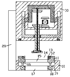
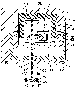
[0011] Combine below Figure 1-2 The present invention will be described in detail.

[0012] refer to Figure 1-2 , an intelligently operated construction equipment according to an embodiment of the present invention, comprising a clamping base 10 and a processing frame 30 installed on the upper side of the clamping base 10 through a support arm 20, the inner wall of the processing frame 30 The body is provided with a sliding cavity 37, and the processing frame 30 at the top of the sliding cavity 37 is provided with a transmission cavity 51, and a U-shaped slide plate 53 is installed in the transmission cavity 51, and the left and right sides of the sliding cavity 37 are The inner wall is symmetrically provided with a control sliding cavity 31 extending upwards. A sliding plate 36 is slidably fitted in the sliding cavity 37, and a control sliding plate fixedly connected with the sliding plate 36 is slidably mounted in the control sliding cavity 31. 35, the control slide cham...


PUM


Abstract

The invention discloses an intelligent control type building facility. The intelligent control type building facility comprises a mounting and clamping base and a processing machine frame, wherein theprocessing machine frame is installed on the upper side of the mounting and clamping base through a supporting arm rod. A sliding cavity is formed in the inner wall body of the processing machine frame, a transmission cavity is formed in the portion, located at the top end of the sliding cavity, of the processing machine frame, and a U-shaped sliding plate is installed in the transmission cavityin a sliding fit mode. Regulation and control sliding cavities which are arranged in an upward extension mode are symmetrically formed in the inner walls of the left side and the right side of the sliding cavity. A sliding plate is installed in the sliding cavity in a sliding fit mode, and regulation and control sliding plates which are fixedly connected with the sliding plate are installed in theregulation and control sliding cavities in a sliding fit mode. Through cavities which are arranged in a left-and-right symmetry mode are arranged between the regulation and control sliding cavities and the transmission cavity in a communicating mode. Driving motors are fixedly arranged in the inner walls of the rear sides of the through cavities, driving gears are fixedly arranged on output shafts at the front ends of the driving motors, and first racks which mesh with the driving gears are arranged on the end faces of the inner sides of the regulation and control sliding plates.

Description

technical field [0001] The invention relates to the technical field of construction, in particular to intelligently controlled construction equipment. Background technique [0002] During the construction process, drilling equipment and grinding equipment are commonly used basic construction equipment. Usually, drilling equipment and grinding equipment need to be switched frequently. At present, the equipment usually only has the function of drilling or grinding, and its function is single. , in the prior art, there are also mutually adjustable ones, but the adjustment operation steps are cumbersome, and the structure is complicated, and the use safety is low. Contents of the invention [0003] The object of the present invention is to provide an intelligently controlled construction equipment for overcoming the above-mentioned defects in the prior art. [0004] An intelligently controlled construction equipment according to the present invention comprises a clamping base...

Claims


Application Information

Patent Timeline
IPC IPC(8): B23P23/04
CPCB23P23/04
Inventor 戎佰腾
Owner 戎佰腾
Why Eureka
Try Eureka