Cutter change mechanism for elevated gantry machining center

A tool changing mechanism and gantry technology, which is applied to metal processing machinery parts, metal processing equipment, manufacturing tools, etc., can solve the problem of not being able to adapt to the tool changing structure, solve the problem of tool magazine location layout and protection layout, and solve the problem of loading and unloading. Workpieces, the effect of improving efficiency and accuracy

Pending Publication Date: 2018-10-12
NINGXIA YINCHUAN DAHE CNC MACHINE
View PDF0 Cites 4 Cited by
  • Summary
  • Abstract
  • Description
  • Claims
  • Application Information

AI Technical Summary

Problems solved by technology

[0003] The automatic tool changer is an essential and important part in automated manufacturing, and has been used in most machine tool industries. However, at present, the tr

Method used


Image

  • Cutter change mechanism for elevated gantry machining center
  • Cutter change mechanism for elevated gantry machining center
  • Cutter change mechanism for elevated gantry machining center

Examples


Embodiment 1

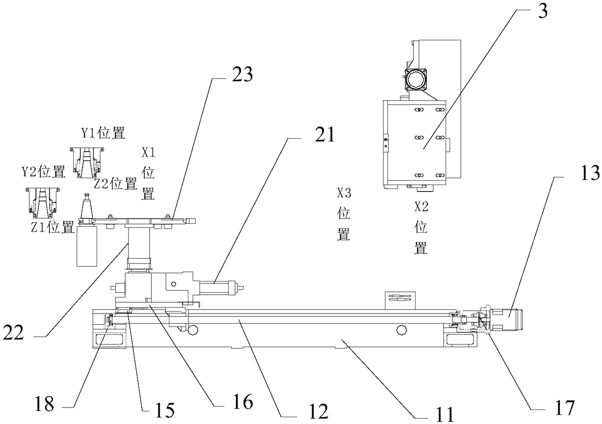
[0025] Such as Figure 1-2 As shown, a tool changing mechanism for an overhead gantry machining center includes a moving device 1 and an ATC manipulator 2 arranged on the moving device 1 .

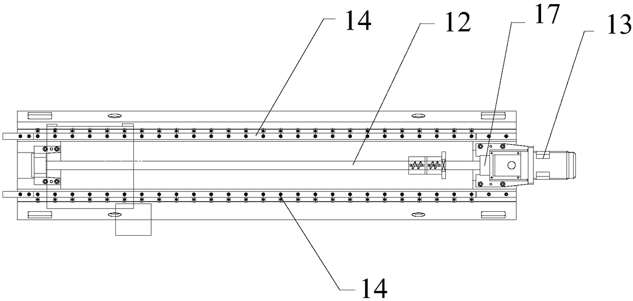
[0026] The moving device 1 includes a frame 11, on which a lead screw 12 is arranged, one end of the lead screw 12 is connected with the output shaft of the servo motor 13 through a coupling 17, and bearings 18 are arranged at both ends of the lead screw 12. Two guide rails 14 parallel to the leading screw 12 are arranged on both sides of the leading screw 12 , a linear slide 15 is arranged on the guide rail 14 , a workbench 16 is arranged on the linear slide 15 , and the lead screw 12 is connected to the lower end of the workbench 16 .

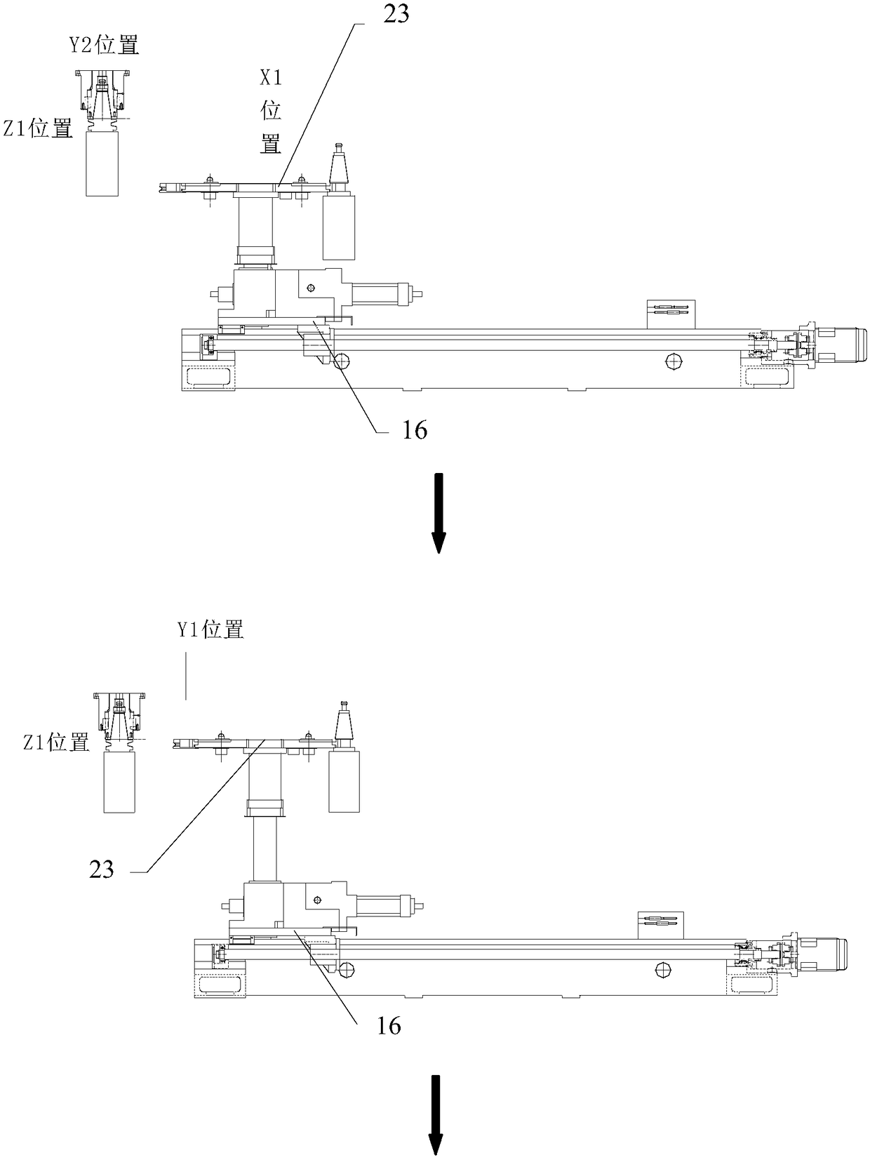
[0027] ATC manipulator 2 comprises the rotary oil cylinder 21 that is arranged on the workbench 16, is arranged on the lift cylinder 22 above the rotary oil cylinder 21 and is arranged on the manipulator 23 that is used for loading and unloading cutter on...


PUM


Abstract

The invention discloses a cutter change mechanism for an elevated gantry machining center. The cutter change mechanism comprises a moving device (1), and an ATC manipulator (2) arranged on the movingdevice (1); the moving device (1) comprises a frame (11) and a lead screw (12); one end of the lead screw (12) is connected with an output shaft of a servo motor (13); two guide rails (14), parallel to the lead screw (12), are arranged on two sides of the lead screw (12); linear slide blocks (15) are arranged on the guide rails (14); a worktable (16) is arranged on the linear slide blocks (15); the lower end of the worktable (16) is connected with the lead screw (12); and the ATC manipulator (2) comprises a rotating device (21), a hoisting device (22) and a manipulator (23) arranged on the worktable (16). Through ordered numerical control and mechanical operation, high efficiency and accuracy of the machining center are greatly improved, the position arrangement problem and the protectionarrangement problem of a cutter magazine are solved, and the workpiece loading and unloading problems in interference of machining of a machine tool are solved.

Description

technical field [0001] The invention relates to the field of tool changing mechanisms for machining centers, in particular to a tool changing mechanism for elevated gantry machining centers. Background technique [0002] The application of automation and intelligence in the machining industry has occupied the entire manufacturing industry, which has enabled the rapid development of the entire machining industry. The use and application of various automatic lines has made our country's manufacturing industry go to the forefront of the world. [0003] The automatic tool changer is an essential and important part in automated manufacturing, and has been used in most machine tool industries. However, at present, the traditional tool change mechanism is used on the gantry machine tool, which cannot adapt to the high-speed and efficient overhead gantry machining center. Tool change structure. Contents of the invention [0004] In order to solve the above problems, the present i...

Claims


Application Information

Patent Timeline
IPC IPC(8): B23Q3/155
CPCB23Q3/15503B23Q3/1554
Inventor 刘波高鹏贤邓立国李世彪
Owner NINGXIA YINCHUAN DAHE CNC MACHINE
Why Eureka
Try Eureka