Limiting device for bent portion of cloth rack conveying chain

A technology for conveying chains and chain curved parts is applied in the field of limit devices, which can solve the problems of inconvenient operation, inability to disengage the clothes hanger rollers, and increase the difficulty of picking up and clipping fabrics, so as to achieve a lightweight and convenient hanging. Effect

Active Publication Date: 2018-10-12
INA INTELLIGENT TECH (ZHEJIANG) CO LTD
View PDF8 Cites 6 Cited by
  • Summary
  • Abstract
  • Description
  • Claims
  • Application Information

AI Technical Summary

Problems solved by technology

The limit device includes a guardrail. The guardrail has an arc-shaped part leaning against the outside of the curved part of the conveyor chain. The guardrail is fixed on the outside of the conveyor chain. In existing applications, the clothes hanger cannot be directly moved from the outside of the conveyor chain hooked to the guardrail
[0004] In the existing hanging system for garment making, the clothes hanger with the cloth is usually only hooked into the hanging system at the first workstation. During the operation of the hanging system, if the hanger falls Usually, the clothes hanger will be sent to the position of the first workstation, so that the clothes hanger can enter the garment hanging system again. The inconvenience of this operation is obvious.
When the conveyor chain is set at the work station as the lifting device for the hanger, the hanger is transported to the workbench, and the hanger roller cannot be disengaged from the conveyor chain, which increases the difficulty of picking and hanging the fabric

Method used


Image

  • Limiting device for bent portion of cloth rack conveying chain
  • Limiting device for bent portion of cloth rack conveying chain
  • Limiting device for bent portion of cloth rack conveying chain

Examples


Embodiment Construction

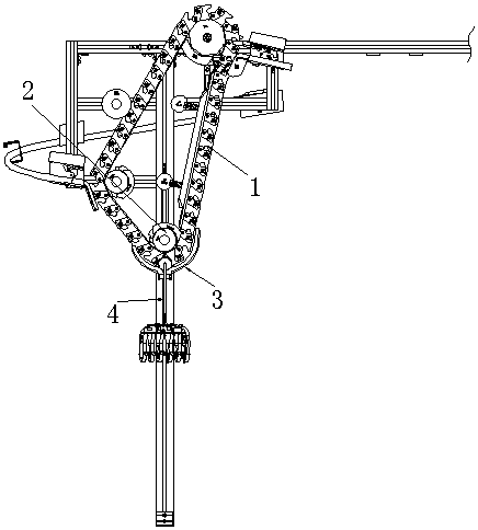
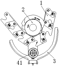
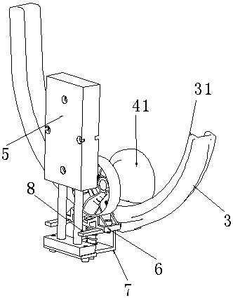
[0025] In conjunction with the accompanying drawings, the limit device for the curved part of the clothes hanger conveying chain is set on the outside of the curved part of the conveying chain 1 in the garment hanging system, which can play a role of limiting, so that the clothes hanger 4 can pass through the guardrail smoothly under the conveying chain 1 3 positions. The conveyor chain 1 is used in the garment hanging system to lift and transport the hangers 4. At the workstation position of the garment hanging system, the connection between the ring rail and the workbench can be established by setting the conveyor chain 1 , to realize the delivery of the clothes hanger 4 between the ring track and the workbench. The conveyor chain 1 is a closed structure composed of several chain plates hinged together head to tail. A clamp for clamping the hanger roller 41 is formed between two adjacent chain plates. The clamp on the straight-line portion of the conveyor chain 1 The mouth ...


PUM


Abstract

The invention discloses a limiting device for the bent portion of a cloth rack conveying chain. A cloth rack can be hang on a guard bar of the limiting device in a connected manner, the use function of the limiting device can be effectively expanded, the structure is simple, and arrangement is convenient. According to the technical scheme, the limiting device for the bent portion of the cloth rackconveying chain is arranged on the outer side in the direction of the bent portion of the cloth rack conveying chain and structurally comprises the guard bar with an arc portion, the conveying chainis formed in the manner that a plurality of chain plates are hinged together in an end-to-end manner, and a clamping opening used for clamping a cloth rack rolling wheel is formed between every two adjacent chain plates. The limiting device for the bent portion of the cloth rack conveying chain is characterized in that the guard bar is connected to a movable type connection structure and used foracting on the connection structure, the guard bar is made to be close to the conveying chain and limits the cloth rack rolling wheel on the conveying chain, so that the conveying chain can convey thecloth rack; or the guard bar is far away from the conveying chain, so that the cloth rack rolling wheel can be connected to the guard bar in a hung manner, and under the push of the guard bar, the cloth rack rolling wheel enters the corresponding clamping opening of the conveying chain.

Description

technical field [0001] The invention relates to a conveying chain used for lifting and conveying clothes hangers in a clothes hanger system, in particular to a limiting device arranged at the direction of the curved part of the conveying chain and used to limit the clothes hangers. Background technique [0002] The garment hanging system is used to distribute the cut fabrics to each workstation, where the fabrics are sewn in one process of garments, and the fabrics are sewn among the workstations in order to complete the preparation of garments. The garment hanging system includes a ring line set at an elevated height. Each workstation is set along the direction of the ring rail. A machine table for the operator to sit is set at the position of the workstation. Compared with the setting height of the ring rail, the position of the machine table is relatively It is relatively low, and the clothes hanger needs to be lifted between the machine platform and the ring rail, which ...

Claims


Application Information

Patent Timeline
Patent Type & Authority Applications(China)
IPC IPC(8): B65G17/20
CPCB65G17/20
Inventor 翁端文周为军
Owner INA INTELLIGENT TECH (ZHEJIANG) CO LTD
Why Eureka
Try Eureka