Bypass flue gas flow spray drying desulfurization wastewater treatment device and method

A desulfurization wastewater and bypass flue technology, applied in the field of environmental engineering, can solve the problems of increased maintenance costs, complex membrane technology systems, affecting the operation of the main engine, etc., to achieve no maintenance, light nozzles, easy to clean and replace. Effect

Active Publication Date: 2020-12-25
SOUTHEAST UNIV +1
View PDF7 Cites 0 Cited by
  • Summary
  • Abstract
  • Description
  • Claims
  • Application Information

AI Technical Summary

Problems solved by technology

[0007] The flue spray evaporation technology has serious fouling and blockage in the flue, which affects the operation of the main engine; the membrane technology system is complicated, the investment is high, and the membrane modules need to be replaced regularly, which leads to increased maintenance costs. -30 yuan / ton, a large amount of sludge containing heavy metals will be generated, which will increase the cost of disposal

Method used


Image

  • Bypass flue gas flow spray drying desulfurization wastewater treatment device and method
  • Bypass flue gas flow spray drying desulfurization wastewater treatment device and method
  • Bypass flue gas flow spray drying desulfurization wastewater treatment device and method

Examples


Embodiment 1

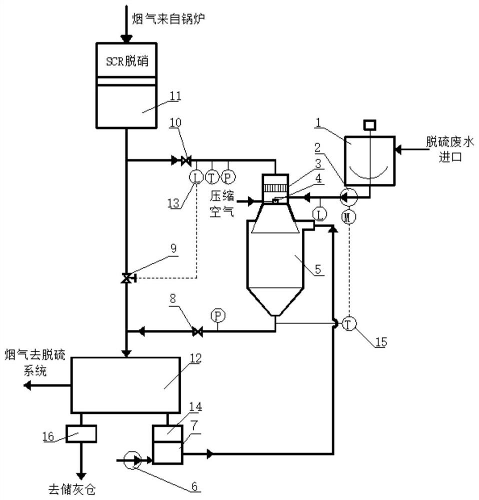
[0036]A bypass flue airflow spray drying desulfurization wastewater treatment method. After the flue gas comes from the boiler air preheater, the temperature is about 120℃. The device is composed of a flue gas distributor 3, an airflow nozzle 4, and an airflow spray tower 5. The lower part of the flue gas distributor 3 is connected with the upper part of the airflow spray tower 5. The airflow nozzle 4 is arranged on the inner central axis of the airflow spray tower 5, and is separated from the flue gas distributor 3 by 100-500mm. The flue gas distributor 3 The inlet flue is equipped with a flue gas flow meter to control the regulating valve 9 on the main flue. The waste water entering the airflow nozzle 4 is sent in by the waste water pump 2, and the flow rate of the waste water pump 2 is determined by the outlet flue temperature at the bottom of the airflow spray tower 5. The meter 15 measures the temperature adjustment, and the outlet smoke thermometer 15 has a temperature adjustm...

Embodiment 2

[0038]A bypass flue airflow spray drying desulfurization wastewater treatment method and device. The flue gas comes from the boiler economizer and after the SCR is out of stock, the temperature is about 350℃. When the boiler is operating under normal load conditions, the resistance of the air preheater is greater than the resistance of the spray tower , Open the regulating valve 9 and adjust the second on-off valve 10 to realize that the measurement value of the flue gas flow meter 13 entering the spray tower reaches the set value. When operating under low load conditions, the resistance of the air preheater is less than the resistance of the spray tower. Open the second switch valve 10, adjust the control valve 9 on the main flue, and also realize that the measurement value of the flue gas flow meter 13 entering the spray tower reaches the set value; the temperature adjustment range of the outlet flue gas thermometer 15 is also 90- 100°C.

Embodiment 3

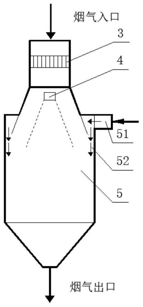
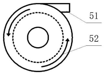
[0040]The bypass flue gas flow spray drying desulfurization wastewater treatment device is composed of a flue gas distributor 3, a gas flow nozzle 4, and a gas spray tower 5. The lower part of the flue gas distributor 3 is connected with the upper part of the gas spray tower 5, and the gas flow nozzle 4 Set on the inner central axis of the airflow spray tower 5, 100-500mm apart from the flue gas distributor 3, the flue gas distributor 3 is equipped with a flue gas flow meter 13 on the flue gas duct to control the regulating valve 9 on the main flue gas duct , The waste water entering the airflow nozzle 4 is sent in by the waste water pump 2, and the flow rate of the waste water pump 2 is adjusted by the metering temperature of the outlet flue gas thermometer 15 provided at the bottom of the airflow spray tower 5. The airflow spray tower 5 is provided with a fly ash inlet 51 on the top of the straight cylinder, and the fly ash inlet 51 is tangentially connected with the airflow spray...


PUM


Abstract

The invention discloses a bypass flue gas spray drying desulphurization waste water processing apparatus and a method thereof. The apparatus comprises an air-flow spraying tower, a flue gas wind distributor arranged at the upper part of the air-flow spraying tower and connected with the air-flow spraying tower, an air-flow nozzle arranged at a central line in the air-flow spraying tower, a waste water pot connected with an air-flow nozzle feed inlet, a deduster connected with the lower part of the air-flow spraying tower, a first ash bin and a second ash bin respectively connected with two ends of the lower part of the deduster, a positive air seal machinery connected with an ash outlet of the second ash bin, and a Roots blower and an air-outlet pipe connected with the lower part of the positive air seal machinery. A fly ash inlet is arranged at the top of a straight tube of the air-flow spraying tower, the fly ash inlet and the straight tube of the air-flow spraying tower are tangentially connected, and the fly ash in the air-flow spraying tower spirally downward sprays. The operation cost is low, no fouling and wall scaling is generated, the system operation is reliable, operation of a boiler main body is not influenced, and the operation is stable and reliable.

Description

Technical field[0001]The invention belongs to the field of environmental engineering, and relates to a device and method for treating desulfurization wastewater from a coal-fired power plant.Background technique[0002]The "Technical Regulations for the Design of Wastewater Treatment in Thermal Power Plants" promulgated in 2006 has clearly stated that the desulfurization wastewater treatment facilities of thermal power plants should be set up separately, treatment and reuse should be given priority, no discharge ports, and zero wastewater discharge must be achieved. Desulfurization wastewater is the terminal wastewater of power plants, and the water quality is the worst. Desulfurization wastewater mainly contains calcium, magnesium ions and chloride ions. The high content of chloride ions makes the desulfurization wastewater unable to be biochemically treated to meet the reuse water standard.[0003]At present, the flue spray evaporation technology, coal field spraying, reverse osmosis ...

Claims


Application Information

Patent Timeline
Patent Type & Authority Patents(China)
IPC IPC(8): C02F1/12C02F103/18
CPCC02F1/12C02F2103/18C02F2201/002C02F2201/007Y02A20/141
Inventor 葛仕福周彩玲沈越
Owner SOUTHEAST UNIV
Why Eureka
Try Eureka