Manual correction device for cantilever steel beam and construction method thereof

A manual, cantilevered technology, applied in the field of manual devices and cantilevered steel beams, can solve the problems of increased construction difficulty, lack of effective support at the cantilevered end, unacceptable and other problems, and achieve accurate and convenient z-direction correction effect Recycling and reuse, the effect of smooth and labor-saving process

Active Publication Date: 2018-10-12
ZHEJIANG ERJIAN STEEL STRUCTURE
View PDF12 Cites 6 Cited by
  • Summary
  • Abstract
  • Description
  • Claims
  • Application Information

AI Technical Summary

Problems solved by technology

[0005] There are many reasons for the above problems. One is that the construction personnel’s specific operation errors lead to the error of the final position of the cantilevered end. The other is that most of the weight of the cantilevered steel girder still remains when the inner end of the cantilevered steel girder is welded and fixed. It is lifted by a crane, and the cantilever end lacks effective support, which makes the construction more difficult and will further enlarge the deviation of the cantilever end; the third and more important reason is that each steel column inevitably has errors in actual construction, and it is impossible Keep it completely vertical, so the top of the steel column has a deviation from inside to outside or from left to right, and the cantilevered beam is welded with the inner end against the top of the steel column and the steel column as the reference plane. Errors will naturally occur. Although the error at the top of the steel column is kept within the acceptable range of construction, after the enlargement of the large-scale and large-volume cantilever beam, it is finally reflected in the error of the outer end of the cantilever beam, that is, the cantilever end. , it will naturally be magnified to an unsightly and unacceptable level

Method used


Image

  • Manual correction device for cantilever steel beam and construction method thereof
  • Manual correction device for cantilever steel beam and construction method thereof
  • Manual correction device for cantilever steel beam and construction method thereof

Examples


Embodiment Construction

[0035] The present invention will be further described below in conjunction with the accompanying drawings and specific embodiments.

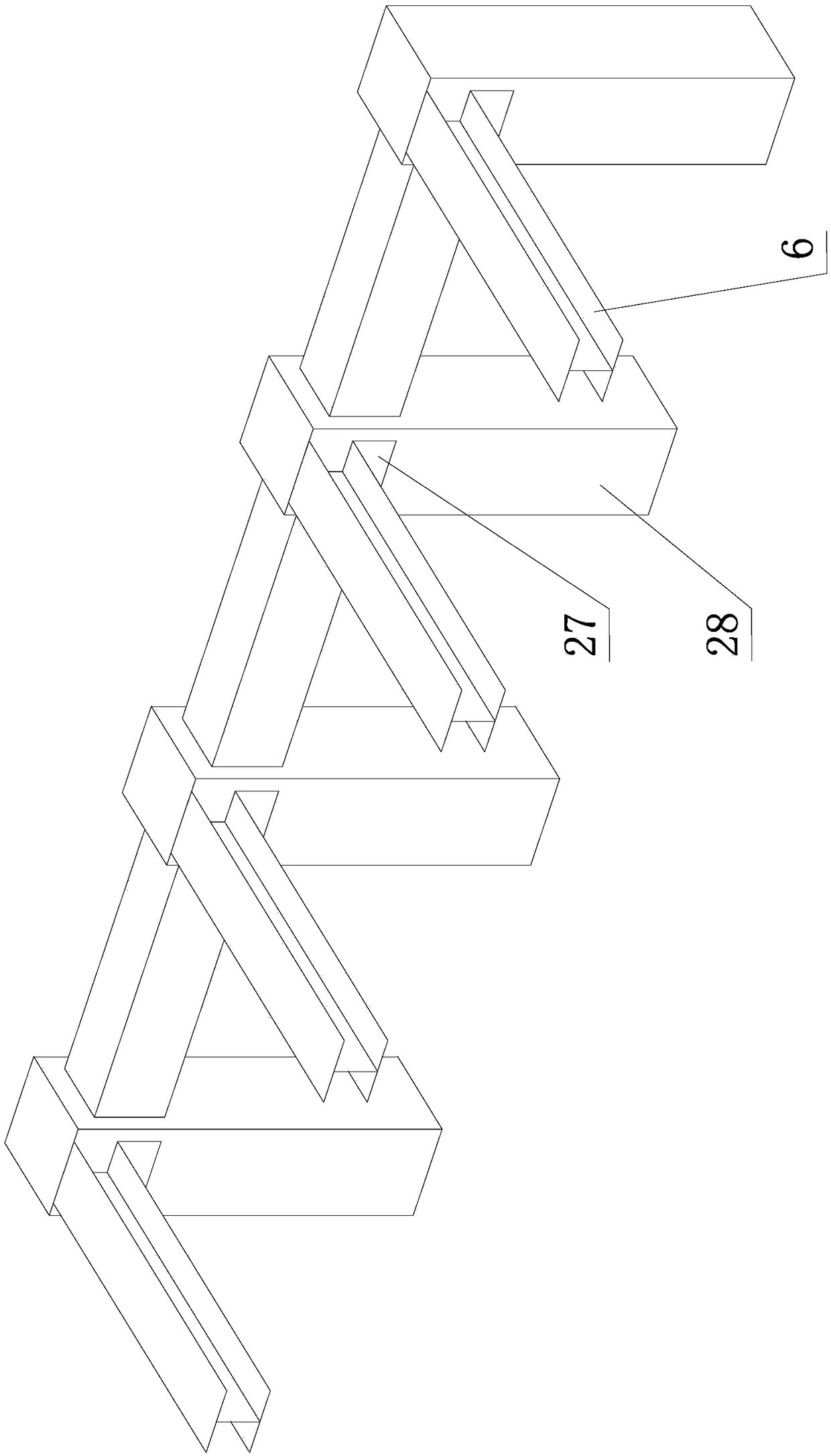
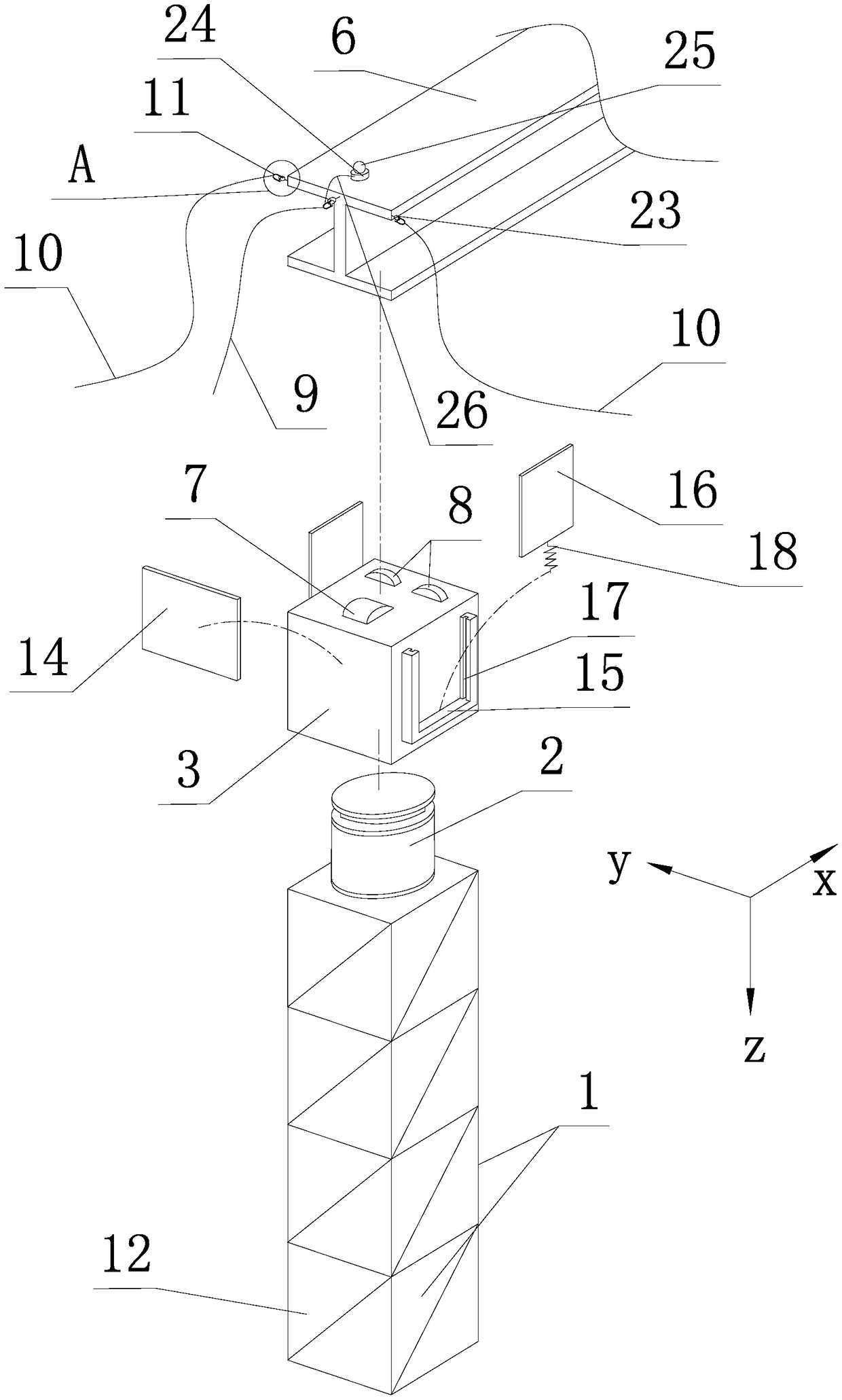
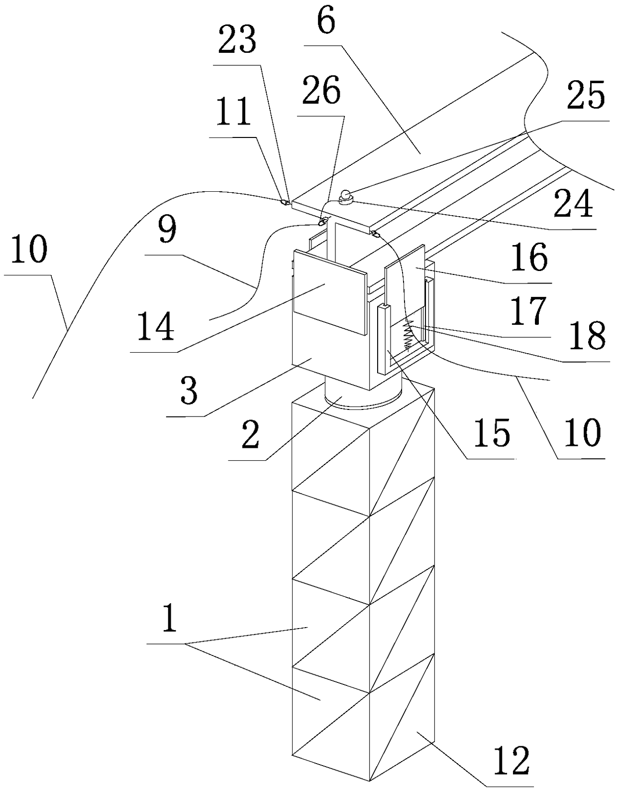
[0036] Such as figure 1 , figure 2 , image 3 , Figure 4 , Figure 5 , Figure 6 Shown, the manual straightening device of cantilever steel beam of the present invention, it comprises support mechanism and traction mechanism.

[0037] The support mechanism includes a support frame 1, a z-direction jack 2 and a jack 3; the support frame 1 is formed by a plurality of steel frame units 12 being screwed up and down. Each unit includes four vertical poles, four upper beams and four lower beams. The above-mentioned vertical poles, upper beams and lower beams are welded into a square frame structure, and six faces of the square frame are provided with a connecting slanting beam. Specifically, four upper beams form the upper frame, four lower beams form the lower frame, and four columns are located at the four corners to connect the upper and l...


PUM


Abstract

The invention discloses a manual correction device for a cantilever steel beam and a construction method. The manual correction device comprises a supporting mechanism and a traction mechanism. The supporting mechanism comprises a supporting frame, a z-direction jack and a plug. The supporting frame is fixed with the plug through the z-direction jack, an x-direction jack and a y-direction jack areinstalled in the plug, x-direction idler wheels for supporting the cantilever end of the cantilever steel beam are rotatably installed on a bracket of the x-direction jack, and y-direction idler wheels for supporting the cantilever end of the cantilever steel beam are rotatably installed on a bracket of the y-direction jack. The traction mechanism comprises an x-direction traction rope and two y-direction traction ropes, and the three traction ropes are detachably connected with the outer end and the left and right sides of the cantilever steel beam through respective rope buckles of the three traction ropes. The key of the manual correction device is to use the two groups of idler wheels to alternately support and lubricate the cantilever end and use the traction ropes to pull for correction. According to the manual correction device and the construction method, the cantilever ends of the cantilever steel beams can be kept aligned in all directions of x, y, and z.

Description

technical field [0001] The invention relates to the technical field of connection construction of truss-type steel structures in civil engineering, and specifically relates to a manual device for correcting the cantilevered end of a cantilevered steel beam when installing a cantilevered steel beam on a section steel column of a truss-type steel structure. A method for constructing cantilevered steel beams by utilizing the device. Background technique [0002] Large-scale venues mostly adopt a truss-type steel structure connected vertically and horizontally by steel beams and section steel columns. In the above-mentioned truss-type steel structure, it is often necessary to construct a cantilevered platform protruding outside to serve as a cantilevered stand or rain shelter. The specific construction method is to connect and fix a row of parallel cantilevered steel beams on the upper part of a row of parallel steel columns, that is, cantilevered steel beams, and then connect t...

Claims


Application Information

Patent Timeline
Patent Type & Authority Applications(China)
IPC IPC(8): E04G21/18E04B1/24
CPCE04B1/24E04G21/18Y02P70/10
Inventor 王剑平王贤权李立谢宝伟张国松
Owner ZHEJIANG ERJIAN STEEL STRUCTURE
Why Eureka
Try Eureka