Hydraulically-driven reciprocating air compressor
A reciprocating air compressor technology, applied in the field of air compressors, can solve problems such as complex structure, unreliability, and reduced production efficiency, and achieve the effect of compact connection structure
- Summary
- Abstract
- Description
- Claims
- Application Information
AI Technical Summary
Problems solved by technology
Method used
Image

Examples
Embodiment Construction
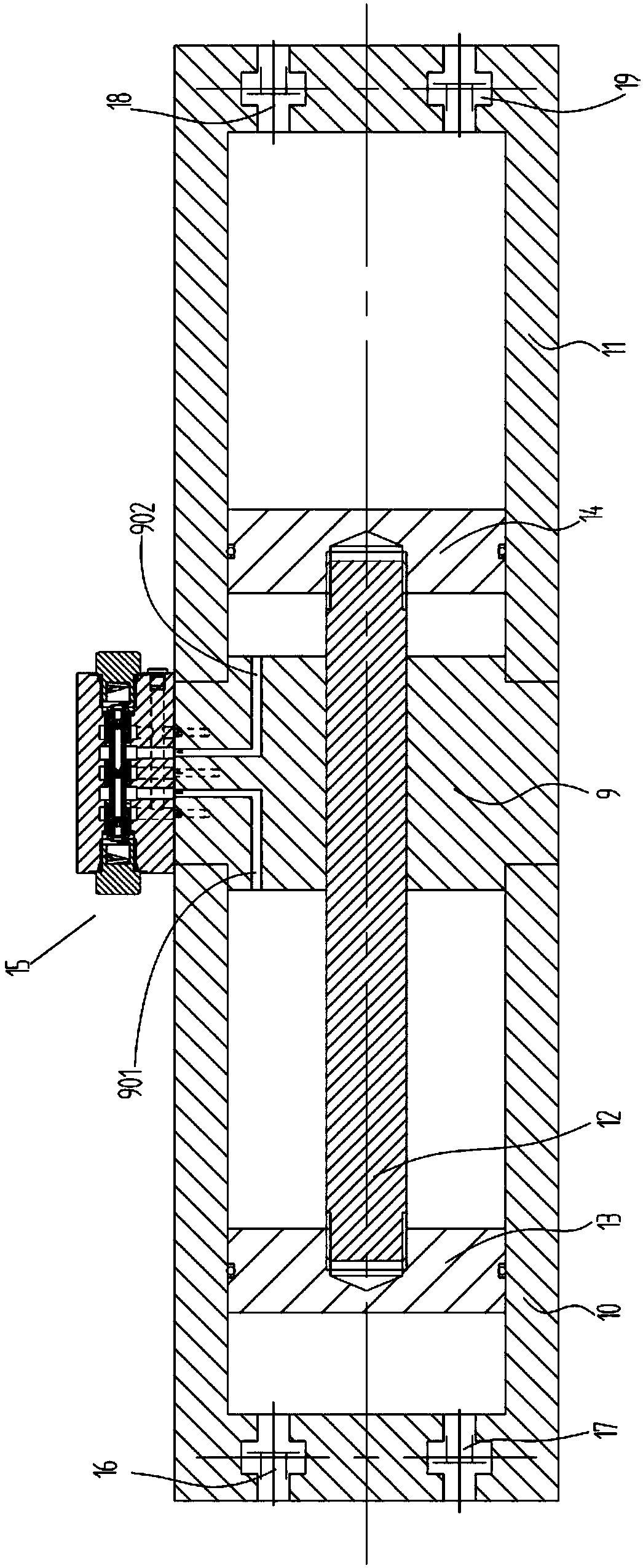
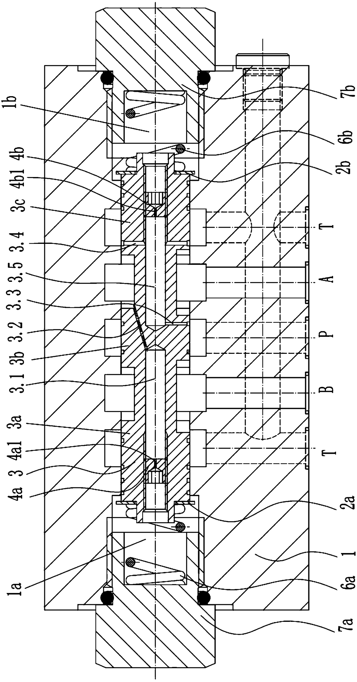
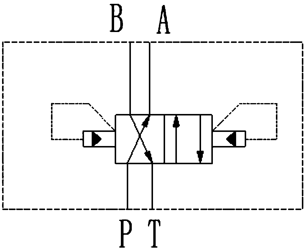
[0016] see Figure 1-3 , the present invention provides a hydraulically driven reciprocating air compressor, including a connecting block 9, the left and right ends of the connecting block 9 are respectively equipped with a first cylinder 10 and a second cylinder 11; Slidingly connected with the piston rod 12, the left end of the piston rod 12 is located in the first cylinder 10, and the right end is located in the second cylinder 11; the first cylinder 10 is slidably connected with the piston The first piston 13 connected to the left end of the rod 12, the second piston 14 connected to the right end of the piston rod 12 is slidably connected in the second cylinder 11; 12 reciprocating reversing valve 15 left and right; the left end of the first cylinder 10 is equipped with a first one-way valve 16 for controlling air entering the rodless cavity of the first cylinder 10 and a first check valve 16 for controlling air discharge. Describe the second one-way valve 17 of the rodle...
PUM
 Abstract
Description
Claims
Application Information
 - Generate Ideas
- Intellectual Property
- Life Sciences
- Materials
- Tech Scout
- Unparalleled Data Quality
- Higher Quality Content
- 60% Fewer Hallucinations
Browse by: Latest US Patents, China's latest patents, Technical Efficacy Thesaurus, Application Domain, Technology Topic, Popular Technical Reports.
© 2025 PatSnap. All rights reserved.Legal|Privacy policy|Modern Slavery Act Transparency Statement|Sitemap|About US| Contact US: help@patsnap.com