Floating type brake pad

A brake pad, floating technology, applied in the direction of brake parts, brake types, brake components, etc., can solve problems such as affecting the braking effect, breaking, and deformation of connecting parts, and achieve the effect of improving the braking effect.

Pending Publication Date: 2018-10-12
BEIJING TIANRENDAOHE NEW MATERIAL CO LTD
View PDF4 Cites 3 Cited by
  • Summary
  • Abstract
  • Description
  • Claims
  • Application Information

AI Technical Summary

Problems solved by technology

[0005] Therefore, the technical problem to be solved by the present invention is to overcome the severe positional deviation along the horizontal direction when the floating brake pads in the prior art are affected by the braking friction or vehicle vibration, resulting in the friction body losing its optimum position. The braking working surface affects the braking effect, and even causes the connecting piece connecting the back plate of the brake pad and the friction body to be deformed or even broken by the shear force, which reduces the braking effect and service life of the brake pad

Method used


Image

  • Floating type brake pad
  • Floating type brake pad
  • Floating type brake pad

Examples


Embodiment 1

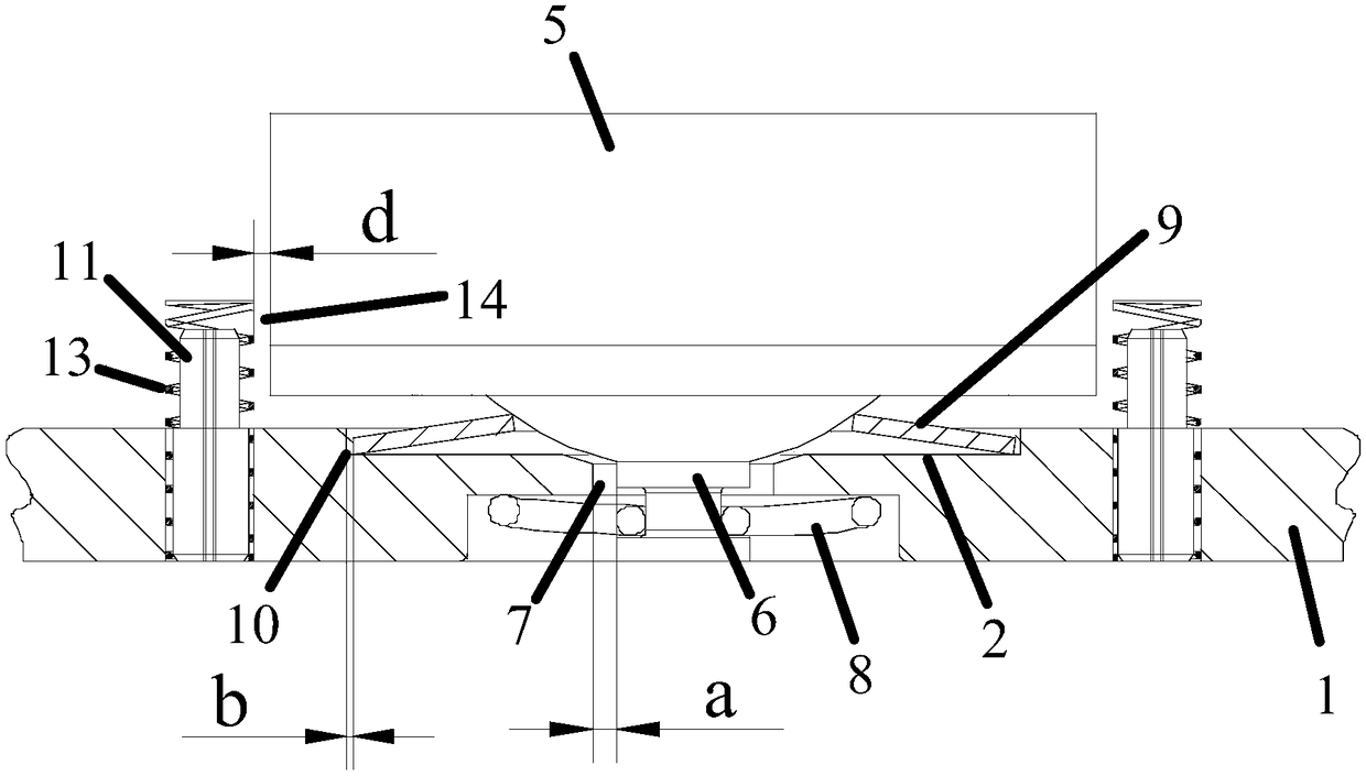
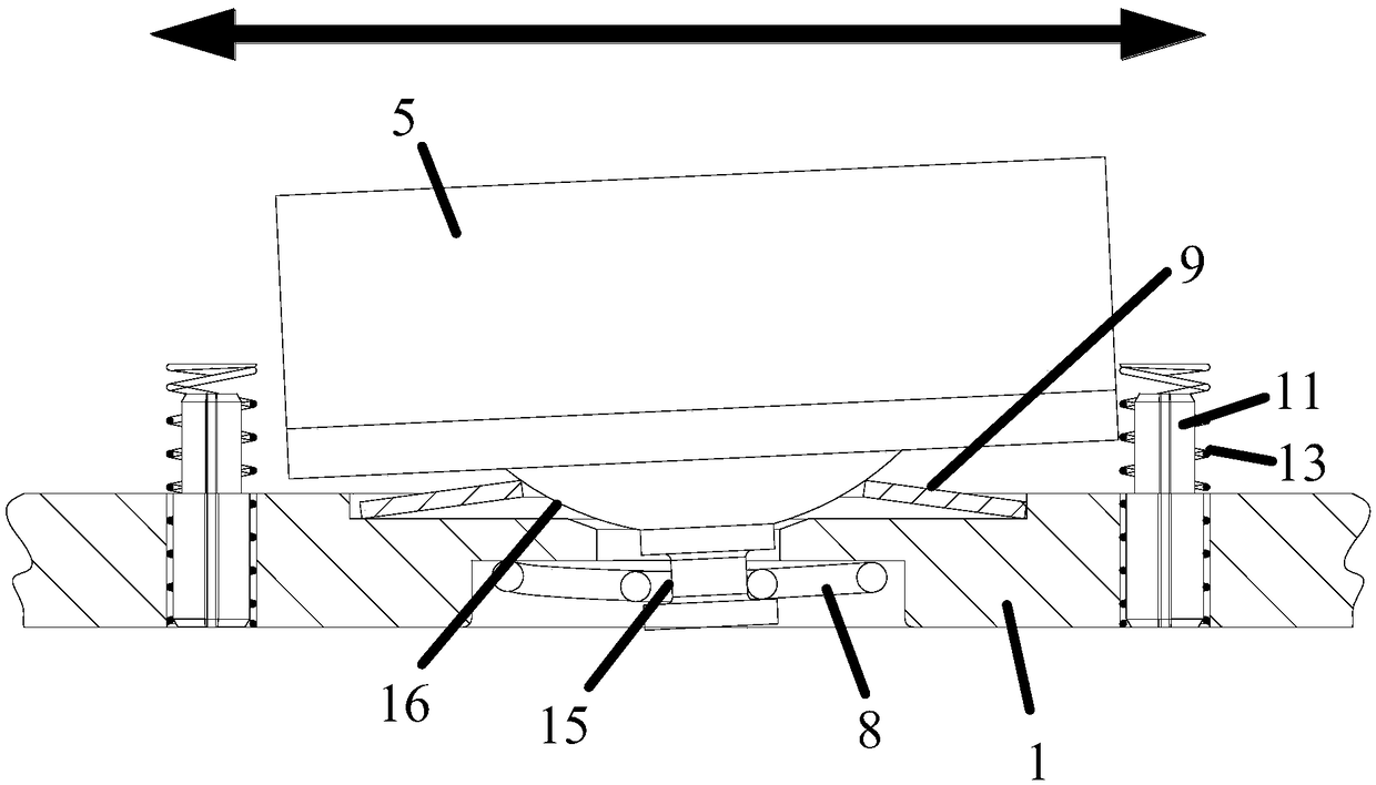
[0041] A floating brake pad is described, such as figure 1 and image 3 shown, which includes:

[0042] Brake back plate 1, said brake back plate 1 is a horseshoe-shaped structure on which a spot-faced plane 2 of a circular structure and a positioning hole 3 of a cylindrical structure are formed;

[0043] The friction body 4 includes a friction part 5, a positioning part 6 inserted into the positioning hole 3, and a spherical support part arranged between the friction part 5 and the positioning part 6 and facing the brake pad back plate 1 16. The positioning part 6 is a cylindrical structure extending from the friction part 5 to the positioning hole 3 and matching with the positioning hole 3. There is a gap between the positioning part 6 and the positioning hole 3 a first relative gap 7 with a relative distance a;

[0044] Elastic support 9, elastic support 9 is a disc-shaped sheet structure connected with the spherical support 16, the elastic support 9 is installed in the ...

Embodiment 2

[0050] The difference between this embodiment and Embodiment 1 is that the outer contour edge of the elastic support member 9 abuts and connects with the inner side wall of the spot facing plane 2, the distance b of the second relative gap 10 is 0, and the first The distance a of the relative gap 7 is greater than the distance d of the fourth relative gap 14 .

Embodiment 3

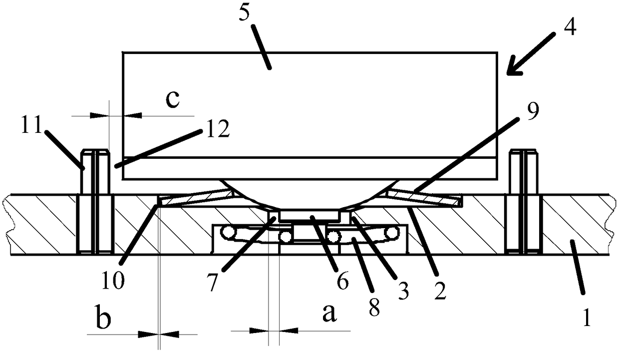
[0052] The difference between this embodiment and embodiment 1 is that, as figure 2 as shown,

[0053] The anti-rotation member 11 is a columnar structure made of spring stainless steel, which is arranged on the brake pad back plate 1 so as to limit the rotation direction of the friction body 4 and control the position of the friction body 4 in the horizontal direction. The position is limited by offset, and there is a third relative gap 12 with a relative distance c between the anti-rotation member 11 and the friction part 5; the distance a of the above-mentioned first relative gap 7 is greater than the distance c of the third relative gap 12 , and the spacing c of the third relative gap 12 is greater than the spacing b of the second relative gap 10, and the hardness value of the compression sleeve 13 is smaller than the hardness value of the anti-rotation member 11, and the anti-rotation member The hardness value of 11 is greater than the hardness value of the elastic supp...


PUM


Abstract

A floating type brake pad comprises a brake pad back plate, a friction body, a connection piece and an elastic supporting piece, wherein the brake pad back plate is provided with a facing plane and apositioning hole; the friction body comprises a friction part and a positioning part inserted into the positioning hole, and a first relative gap exists between the positioning part and the positioning hole; through the connection piece, the friction body is arranged on the brake pad back plate in a floating mode; and the elastic supporting piece is installed in the facing plane and connected withthe friction body, a guide hole suitable for allowing the positioning part to pass is formed in the elastic supporting piece, and the edge of the outline of the elastic supporting piece abuts againstthe inner side wall of the facing plane, or a second relative gap smaller than the first relative gap is formed between the edge of the outline of the elastic supporting piece and the inner side wallof the facing plane. The problems that an existing floating type brake pad is seriously deflected in the horizontal direction when being influenced by the action of brake friction force or vehicle vibration, thus, a friction body loses the best brake working surface, the brake effect is influenced, a connection piece connected with a brake pad back plate and the friction body is deformed and evenbroken due to shear force, the brake effect of the brake pad is reduced, and the service life of the brake pad is shortened are solved.

Description

technical field [0001] The invention relates to the technical field of brake devices, in particular to a floating brake pad. Background technique [0002] At present, in train brakes, a disc brake structure is usually used. The disc brake structure mainly includes a brake disc and a floating brake pad. The above brake structure consumes the kinetic energy of the moving vehicle or equipment through the mutual friction between the brake disc and the floating brake pad to stop the train. sports. The braking effect, durability and production cost of floating brake pads are important indicators to measure the quality of train brakes. [0003] In order to improve the poor braking effect of floating brake pads and to freely adjust the friction block to the optimum working surface, Chinese patent document CN107939874A discloses a floating brake pad, such as image 3 As shown, it includes: a back plate 101; a number of friction blocks 102, which can be floatingly connected to the b...

Claims


Application Information

Patent Timeline
Patent Type & Authority Applications(China)
IPC IPC(8): F16D65/02
CPCF16D65/02F16D65/092F16D65/097F16D69/0408F16D2069/0433F16D69/04F16D2069/0458F16D65/04
Inventor 吴佩芳释加才让胡晨曹静武龙波
Owner BEIJING TIANRENDAOHE NEW MATERIAL CO LTD
Why Eureka
Try Eureka