Straight-tube-type front shock absorber with high performance

A front shock absorber, high-performance technology, applied in the direction of shock absorber, spring/shock absorber, shock absorber, etc., can solve the problems of safety hazard, high production cost, poor buffer function, etc., and reduce the probability of friction , Improve the performance and ensure the effect of shock absorption performance

Inactive Publication Date: 2018-10-12
喻建中
View PDF6 Cites 2 Cited by
  • Summary
  • Abstract
  • Description
  • Claims
  • Application Information

AI Technical Summary

Problems solved by technology

[0002] The front shock absorber is a device used for shock absorption, which is often used in the lower part of vehicles such as motorcycles, electric vehicles, and bicycles. The traditional front shock absorber passes through the buffer seat, buffer bushing, gear ring, and saddle elastic valve. A complete valve system is composed of several parts such as the disc, the gear ring seat, etc. Although this structure has a good buffer function, due to the large number of parts involved, the production cost is extremely high and problems are prone to occur. In order to solve the above problems Generally, the production cost is reduced by canceling the buffer seat and buffer bushing. With the reduction of parts, the possibility of problems with the front shock absorber is also reduced. However, the buffer function of this structure is extremely poor. When encountering a severe impact, there will be a feeling of rigid impact, which increases the possibility of injury to the cyclist, resulting in extremely low riding safety. In severe cases, it may even pose a threat to the personal safety of the cyclist. serious safety hazard

Method used


Image

  • Straight-tube-type front shock absorber with high performance
  • Straight-tube-type front shock absorber with high performance
  • Straight-tube-type front shock absorber with high performance

Examples


Embodiment Construction

[0024] Below in conjunction with accompanying drawing and specific embodiment the present invention will be described in further detail:

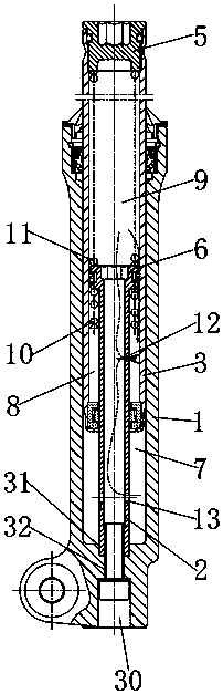
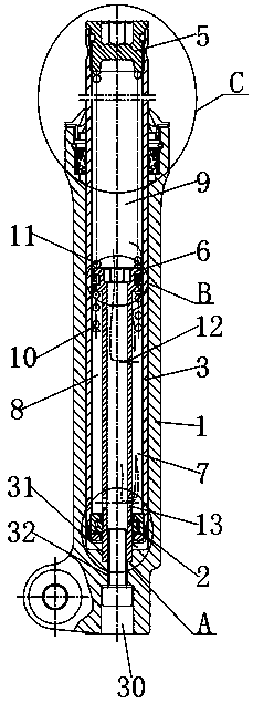
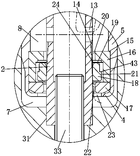
[0025] see Figure 1 to Figure 8 , the present invention provides a high-performance straight-tube front shock absorber, which includes a cylinder body 1, a piston tube 2 disposed inside the cylinder body 1, and a front fork tube 3 sleeved outside the piston tube 2, and the front fork tube 3 The lower end is provided with a recovery valve 4, the upper end of the front fork tube 3 is screwed with a screw plug 5, the upper end of the piston tube 2 is provided with a piston head 6 matching the internal pipeline of the front fork tube 3, the recovery valve 4, the inner wall of the cylinder body 1 and The outer wall of the piston tube 2 is enclosed to form a compression chamber 7, the inner wall of the front fork tube 3, the outer wall of the piston tube 2, the piston head 6 and the recovery valve member 4 are enclosed to form a recovery chamber...


PUM


Abstract

A straight-tube-type front shock absorber with high performance comprises a tube body, a piston pipe arranged in the tube body and a front fork pipe arranged on the exterior of the piston pipe in a sleeving mode. A restoration valve is arranged at the lower end of the front fork pipe, a screw plug is connected to the upper end of the front fork pipe in a screwed mode, and a piston head matched with the restoration valve is arranged at the upper end of the piston pipe. The restoration valve, the inner wall of the tube body and the outer wall of the piston pipe define a compression cavity, the inner wall of the front fork pipe, the outer wall of the piston pipe, the piston head and the restoration valve define a restoration cavity, and an oil storage cavity is defined among the screw plug, the inner wall of the front fork pipe and the piston head. A first spring is arranged in the restoration cavity, a second spring is arranged in the oil storage cavity, and a damping hole is formed in one side of the upper portion of the piston pipe. According to the straight-tube-type front shock absorber with the high performance, the buffering function can be ensured while the production cost isreduced, and thus the performance of the straight-tube-type front shock absorber is ensured.

Description

technical field [0001] The invention relates to a straight-tube front shock absorber, in particular to a straight-tube front shock absorber with high performance. Background technique [0002] The front shock absorber is a device used for shock absorption, which is often used in the lower part of vehicles such as motorcycles, electric vehicles, and bicycles. The traditional front shock absorber passes through the buffer seat, buffer bushing, gear ring, and saddle elastic valve. A complete valve system is composed of several parts such as the disc, the gear ring seat, etc. Although this structure has a good buffer function, due to the large number of parts involved, the production cost is extremely high and problems are prone to occur. In order to solve the above problems Generally, the production cost is reduced by canceling the buffer seat and buffer bushing. With the reduction of parts, the possibility of problems with the front shock absorber is also reduced. However, the...

Claims


Application Information

Patent Timeline
Patent Type & Authority Applications(China)
IPC IPC(8): F16F9/14F16F9/32
CPCF16F9/14F16F9/3207F16F9/3214
Inventor 喻建中
Owner 喻建中
Why Eureka
Try Eureka