
Chemical fiber cloth drying device

A cloth drying and chemical fiber technology, which is applied in the directions of drying, dryer, drying gas arrangement, etc., can solve the problems of excessive humidity of chemical fiber cloth, reducing the practicability of the device, and increasing the limitations of the device, so as to reduce the limitations, The effect of enhanced ventilation, increased flexibility and practicality

Inactive Publication Date: 2018-10-12
湖州春芽针织制衣有限公司
View PDF0 Cites 3 Cited by
  • Summary
  • Abstract
  • Description
  • Claims
  • Application Information

AI Technical Summary

Problems solved by technology

[0002] Chemical fibers are made of natural polymers or artificially synthesized polymers as raw materials, and are produced through the processes of spinning dope, spinning and post-treatment. After chemical fibers are processed into fabrics, they are prone to environmental damage. And the weather factors cause the cloth to have moisture, so the corresponding drying device is needed to dry the chemical fiber cloth, but the existing chemical fiber cloth drying device is relatively lacking, the drying performance is relatively simple, and there are certain deficiencies in the operation. At the same time, the traditional drying device basically uses a fan to dry. Although this achieves the purpose of drying, it is easy to cause slow drying efficiency and poor drying quality, which reduces the practicability of the device. And under the influence of weather factors, the humidity of the chemical fiber cloth is too heavy to be dried quickly, which reduces the practicability of the device, and the traditional drying device can only dry the rolled chemical fiber cloth, and cannot dry the scattered cloth. Automatic drying, increasing the limitations of the device

Method used

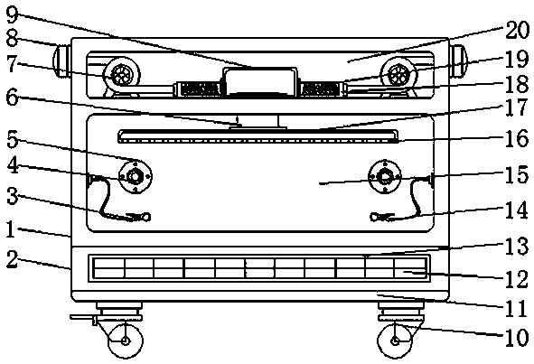
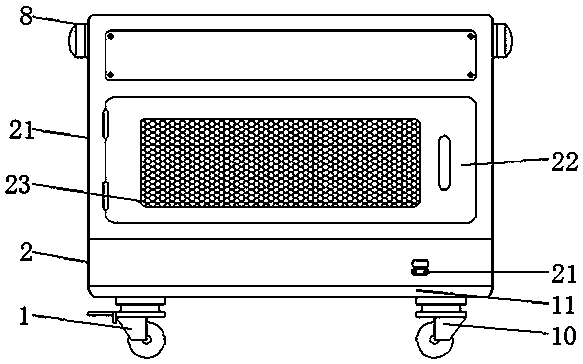
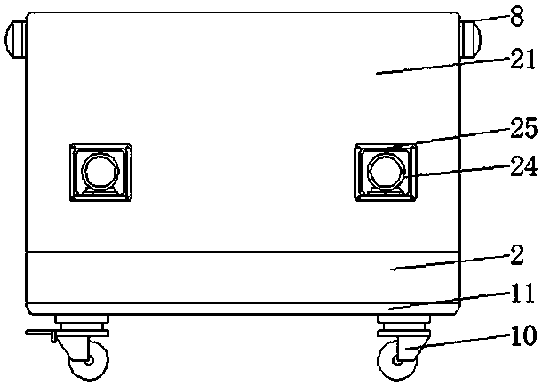

Image

  • Chemical fiber cloth drying device
  • Chemical fiber cloth drying device
  • Chemical fiber cloth drying device

Examples


Embodiment Construction

[0015] The following will clearly and completely describe the technical solutions in the embodiments of the present invention with reference to the accompanying drawings in the embodiments of the present invention. Obviously, the described embodiments are only some, not all, embodiments of the present invention. Based on the embodiments of the present invention, all other embodiments obtained by persons of ordinary skill in the art without making creative efforts belong to the protection scope of the present invention.

[0016] see Figure 1-3 , an embodiment provided by the present invention: a chemical fiber cloth drying device, including a housing 1, a base 2, a fan 7, a bottom plate 11 and a second air guide chamber 17, a bottom plate 11 is installed on the bottom of the base 2, and the bottom plate 11 Walking wheels 10 are installed at the bottom of the car. The walking wheels 10 make the device more convenient to use. The staff can transfer the device according to the ac...


PUM


Abstract

The invention discloses a chemical fiber cloth drying device which comprises a shell, a base, a draught fan, a base plate and a second air guide cavity. The base plate is installed at the bottom of the base, walking wheels are installed at the bottom of the base plate, a containing groove is arranged inside the base, a storage battery is installed inside the containing groove, the shell is installed at the top of the base, a drying chamber is arranged inside the shell, and fixing clamps are installed on the two side walls of the interior of the drying chamber through connecting lines. The chemical fiber cloth drying device is composed of a series of structures including the shell, the base, the draught fan, the base plate, the second air guide cavity and the like, the second air guide cavity enables the device to achieve the even drying effect through a through hole, the draught fan strengthens the ventilation quantity inside the device, a heating pipe can heat guided-in air through aresistance heating wire, the fixing clamps can clamp some scattered chemical fiber cloth, the operation scope of the device is enlarged, the boundedness is reduced, the practicability is high, and thechemical fiber cloth drying device is worthy of use and popularization.

Description

technical field [0001] The invention relates to the field of cloth drying devices, in particular to a chemical fiber cloth drying device. Background technique [0002] Chemical fibers are made of natural polymers or artificially synthesized polymers as raw materials, and are produced through the processes of spinning dope, spinning and post-treatment. After chemical fibers are processed into fabrics, they are prone to environmental damage. And the weather factors cause the cloth to have moisture, so the corresponding drying device is needed to dry the chemical fiber cloth, but the existing chemical fiber cloth drying device is relatively lacking, the drying performance is relatively simple, and there are certain deficiencies in the operation. At the same time, the traditional drying device basically uses a fan to dry. Although this achieves the purpose of drying, it is easy to cause slow drying efficiency and poor drying quality, which reduces the practicability of the devic...

Claims


Application Information

Patent Timeline
IPC IPC(8): F26B13/04F26B13/14F26B21/00F26B25/06F26B25/12
CPCF26B13/00F26B13/14F26B21/001F26B21/004F26B25/063F26B25/12
Inventor 朱振华
Owner 湖州春芽针织制衣有限公司
Learn More