
Automatic Calibration Device and Calibration Method for Convexity Meter

An automatic calibration, convexity meter technology, applied in measuring devices, instruments, using wave/particle radiation, etc., can solve the problem of no convexity meter, and achieve the effect of reducing labor intensity, reducing the risk of radiation, and improving efficiency

Active Publication Date: 2021-02-05
MCC BAOSTEEL TECH SERVICE
View PDF9 Cites 0 Cited by
  • Summary
  • Abstract
  • Description
  • Claims
  • Application Information

AI Technical Summary

Problems solved by technology

However, there is currently no calibration equipment for the convexity meter on the market

Method used


Image

  • Automatic Calibration Device and Calibration Method for Convexity Meter
  • Automatic Calibration Device and Calibration Method for Convexity Meter
  • Automatic Calibration Device and Calibration Method for Convexity Meter

Examples


Embodiment Construction

[0046] The implementation of the present invention will be illustrated by specific specific examples below, and those skilled in the art can easily understand other advantages and effects of the present invention from the contents disclosed in this specification.

[0047] It should be noted that the structures, proportions, sizes, etc. shown in the drawings attached to this specification are only used to match the content disclosed in the specification, for those who are familiar with this technology to understand and read, and are not used to limit the implementation of the present invention. Limiting conditions, so there is no technical substantive meaning, any modification of structure, change of proportional relationship or adjustment of size, without affecting the effect and purpose of the present invention, should still fall within the scope of the present invention. within the scope covered by the disclosed technical content. At the same time, terms such as "upper", "lo...


PUM


Abstract

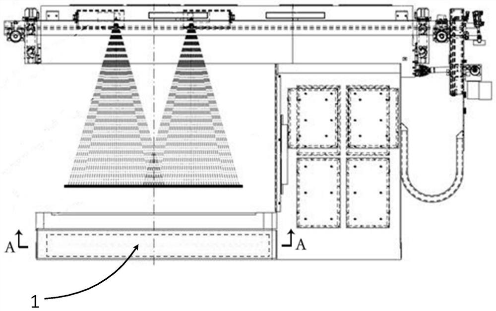
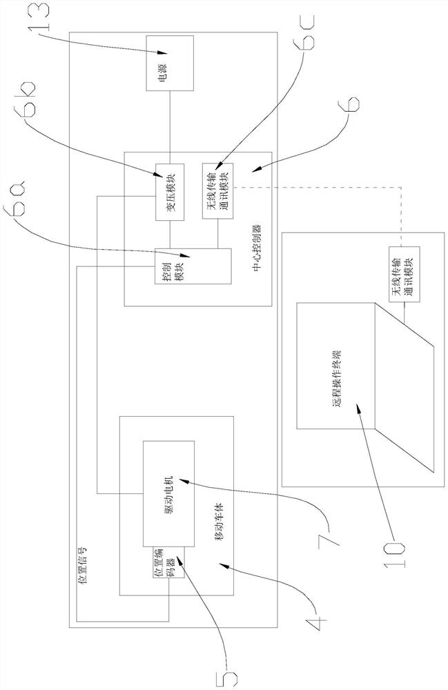
The invention provides a profile gaugemeter automatic calibration device and a calibration method. The device comprises a scale frame erected above a profile gaugemeter radiation detection area, a mobile vehicle body used for carrying a standard model, and a drive mechanism having a position encoder, wherein each tick mark on the scale frame represents a position of the ionization chamber in the profile gaugemeter radiation detection area, and the mobile vehicle body can be movably disposed on the scale frame in a direction along the arrangement of the tick marks, the position encoder is connected to a central controller, and when the central controller issues an instruction to the position encoder, the drive mechanism drives the mobile vehicle body to move to the tick marks to be calibrated. The profile gaugemeter automatic calibration device and the calibration method can remotely operate the movement and positioning of the standard template, and can quickly correct the thickness compensation parameters of the respective ionization chambers of the profile gaugemeter.

Description

technical field [0001] The invention relates to the field of plate detection, in particular to an automatic calibration device and calibration method for a crown meter. Background technique [0002] The crown meter equipment is mainly used to measure the thickness of the steel plate section after finishing rolling in the hot rolling production line. The crown meter equipment measures the thickness of multiple points on the cross section of the steel plate, then collects and integrates the data, and finally displays the crown curve of the steel plate cross section on the inspection screen. It is an important precision instrument equipment for the quality inspection of hot continuous rolling coils. Such as figure 1 and figure 2 , its working principle is that the X-rays generated by the high-voltage X-ray tube of the equipment irradiate the entire steel plate section, and the rays passing through the steel plate are respectively received by multiple ionization chambers 1a a...

Claims


Application Information

Patent Timeline
Patent Type & Authority Patents(China)
IPC IPC(8): G01B15/02
CPCG01B15/02
Inventor 张华雄宋陈朱栋刘卫王子新
Owner MCC BAOSTEEL TECH SERVICE
Learn More