Detachable handle for server chassis
A server and chassis technology, applied in the direction of instruments, electrical digital data processing, digital data processing components, etc., can solve the problems of restricting the surrounding structure design, occupying the space of the chassis, etc., and achieve the effects of heat dissipation, saving time and avoiding interference
- Summary
- Abstract
- Description
- Claims
- Application Information
AI Technical Summary
Problems solved by technology
Method used
Image
Examples
Embodiment 1
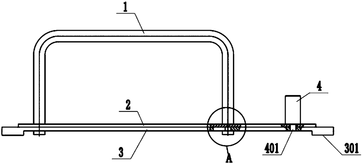
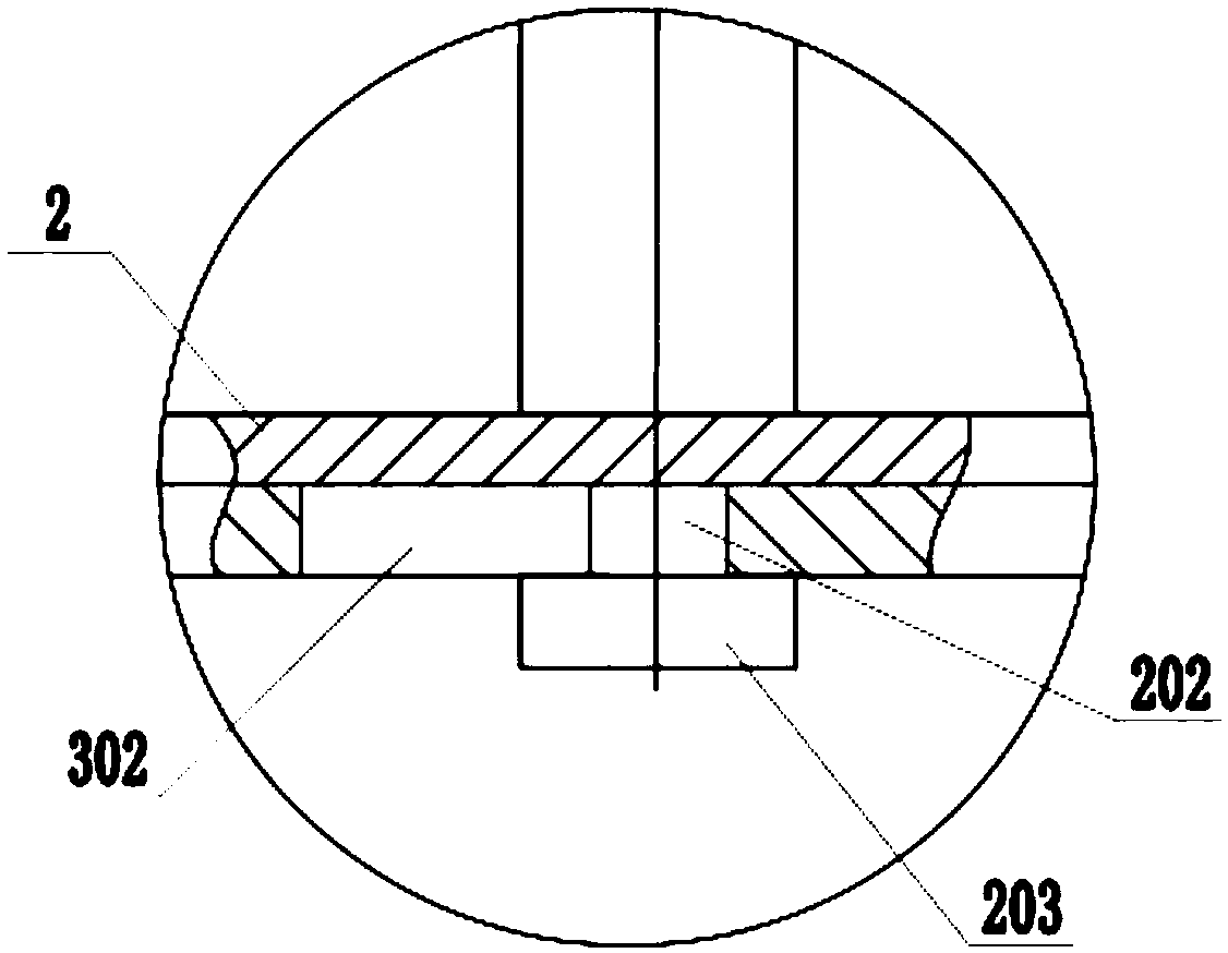
[0032] Such as figure 1 As shown, a detachable handle for a server case includes a handle 1, a connecting plate 2, a mounting base plate 3, and a positioning column 4. Both the mounting base plate 3 and the connecting plate 2 are made of the same steel as the server case, and the thickness of the steel is Similarly, the installation base plate 3 is connected to the server chassis, and the connection position between the installation base plate 3 and the server is selected according to the use requirements, and fixed by welding. The position of the installation base plate 3 cannot hinder the connection of the board. Gourd hole 302 and fixing hole 303, such as Figure 4 As shown, the upper end of the connecting plate 2 is connected with the handle 1, and the handle 1 adopts a hollow design to reduce weight, save materials, and reduce costs. The lower end of the connecting plate 2 is provided with a connecting column 202, and the lower end of the connecting column 202 is provided...
Embodiment 2
[0035] Embodiment 2 is compared with Embodiment 1, the difference lies in the structure and connection method of the positioning column 4 .
[0036] Such as Figure 7 , Figure 9 As shown, the positioning column 4 includes a connection block 402, a connection sleeve 403, and a movable pin 404. The inside of the connection sleeve 403 is provided with an installation cavity 405, and the lower end of the installation cavity 405 is an open structure, and the upper end surface of the connection sleeve 403 is provided with a connection Sleeve hole 411, the connection sleeve hole 411 communicates with the installation cavity 405, the lower end surface of the connection sleeve 403 is welded and fixed with the upper end surface of the connection plate 2, the installation cavity 405 is located at the upper end of the fixing hole 303, and the movable pin 404 includes a sliding Rod 406, the upper end of slide bar 406 is provided with upper fixed head 409, and the lower end of slide bar 4...
Embodiment 3
[0039] The difference between the third embodiment and the second embodiment is that the elastic parts used between the upper inner wall of the connecting sleeve 403 and the sliding rod 406 are different.
[0040] Such as Figure 8As shown, the elastic component is a spring leaf 410 . When installing the handle 1, press the connection plate 2 on the installation base plate 3, make the connection column 202 cooperate with the gourd hole 302, and fix the clamping plate 203 at the lower end of the installation base plate 3, while the lower fixing head 407 is pressed by the installation base plate 3 In the connecting sleeve 403 , the handle 1 is pushed to align the connecting hole 201 with the fixing hole 303 , and under the action of the spring piece 410 , the lower fixing head 407 is inserted into the fixing hole 303 and the handle 1 is fixed.
PUM
 Abstract
Description
Claims
Application Information
 - R&D
- Intellectual Property
- Life Sciences
- Materials
- Tech Scout
- Unparalleled Data Quality
- Higher Quality Content
- 60% Fewer Hallucinations
Browse by: Latest US Patents, China's latest patents, Technical Efficacy Thesaurus, Application Domain, Technology Topic, Popular Technical Reports.
© 2025 PatSnap. All rights reserved.Legal|Privacy policy|Modern Slavery Act Transparency Statement|Sitemap|About US| Contact US: help@patsnap.com


