Synchronously-triggered pulse signal regeneration device and operation method thereof

A technology of synchronous trigger pulse and signal regeneration, applied in instruments, electrical and digital data processing, etc., it can solve the problem of inability to meet the operating efficiency and accuracy requirements of high-precision timing control systems, difficult alignment of clock signals, and resolution of only 10ns, etc. question

Active Publication Date: 2018-10-12
NO 34 RES INST OF CHINA ELECTRONICS TECH GRP
View PDF11 Cites 7 Cited by
  • Summary
  • Abstract
  • Description
  • Claims
  • Application Information

AI Technical Summary

Problems solved by technology

But even with a 100MHz high-end counter, its resolution can only reach 10ns at the highest
Moreover, because the input trigger pulse signal is difficult to align with the clock signal, there will be a δt (0<δt<10ns) time jitter between the output trigger pulse signal and the input trigger pulse signal
Therefore, the existing trigger pulse signal regeneration device cannot meet the requirements of high-precision timing control system operating efficiency and accuracy, and a new technical solution is urgently needed to effectively improve the resolution of the trigger pulse signal and reduce time jitter

Method used


Image

  • Synchronously-triggered pulse signal regeneration device and operation method thereof
  • Synchronously-triggered pulse signal regeneration device and operation method thereof

Examples


Embodiment Construction

[0056] The present invention will be described in detail below in conjunction with the accompanying drawings and specific embodiments.

[0057] Embodiment of synchronous trigger pulse signal regeneration device

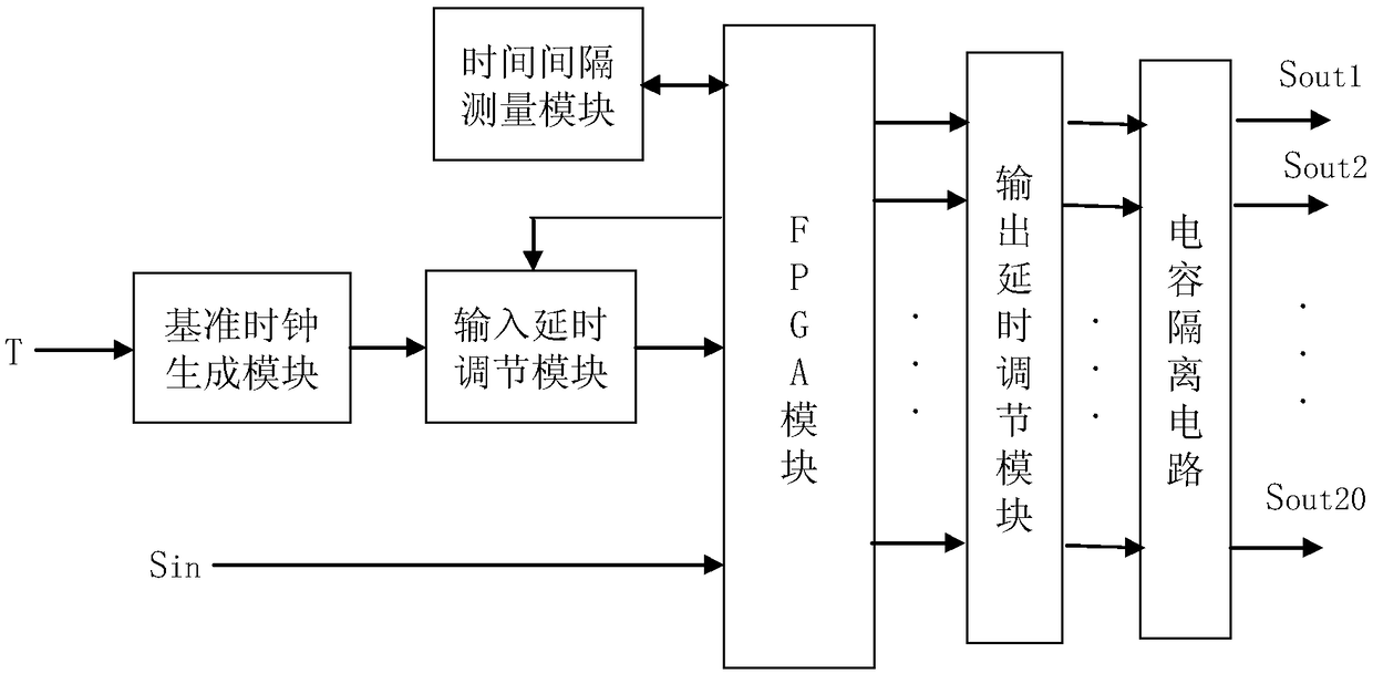
[0058] The overall structural block diagram of the embodiment of the synchronous trigger pulse signal regeneration device is as follows: figure 1 As shown, it includes a reference clock generation module, a time interval measurement module, an input delay adjustment module, an output delay adjustment module and an FPGA module.

[0059] The external clock signal is input to the reference clock generation module, the output of the reference clock generation module is connected to the input delay adjustment module, the output of the input delay adjustment module is connected to the FPGA general IO pin, and the input synchronous trigger pulse signal S in Connect to the general IO pin of the FPGA module, and the time interval measurement module is also connected to the ge...


PUM


Abstract

The invention discloses a synchronously-triggered pulse signal regeneration device and an operation method thereof. The device comprises a reference clock generation module, a time interval measurement module, an input delay regulation module, an output delay regulation module and an FPGA module. According to the operation method of the device, the reference clock generation module tracks and locks an input clock signal and generates a system clock signal; the time interval measurement module measures the time difference between a reference clock signal and an external synchronously-triggeredsignal and calculates a delay control quantity; and the FPGA module regulates a delay value of the input delay regulation module according to the delay control quantity. Through the device and the method, the synchronously-triggered pulse signal is regenerated, multiple synchronously-triggered pulse signals are output, the repetition frequency, pulse width and delay of the signals can be regulatedindependently, it is ensured that the phase difference between the synchronously-triggered pulse signal output after power-on every time and the input pulse signal is smaller than 200ps, delay regulation resolution is improved, and time jitter between output and input of the synchronously-triggered pulse signals is reduced.

Description

technical field [0001] The invention relates to a synchronous trigger pulse technology, in particular to a synchronous trigger pulse signal regeneration device and an operating method thereof. Background technique [0002] In systems that require precise timing control, such as high-speed photography systems, high-speed data acquisition, medical equipment, and energy, the synchronization system is a vital link to maintain their normal operation. Some even require that the synchronous system must have low trigger jitter (less than 500ps), a wide range of pulse width and delay adjustment, and the delay adjustment must have picosecond-level resolution. As a component of a synchronous system, the synchronous trigger pulse signal regeneration device has a direct impact on the operating efficiency and accuracy of these large-scale systems. At present, the trigger pulse signal regeneration is usually realized by the counter method. But even with a high-end counter of 100MHz, its ...

Claims


Application Information

Patent Timeline
Patent Type & Authority Applications(China)
IPC IPC(8): G06F13/40
CPCG06F13/4022G06F13/4068G06F2213/0026G06F2213/0002
Inventor 王航陈峰许党朋赵灏吕宏伟眭明韦佳天谢征田小程张新立杨小亮
Owner NO 34 RES INST OF CHINA ELECTRONICS TECH GRP
Why Eureka
Try Eureka