Confirmation method and device for wind load form factor of steel pipe power transmission tower structure

A technology of shape coefficient and transmission tower, which is applied in the direction of electrical digital data processing, special data processing applications, instruments, etc., can solve the problem of wind load value deviation, low accuracy of wind load shape coefficient of steel pipe transmission tower, Reynolds number, etc. Effect factors such as incomplete consideration, to achieve the effect of improving accuracy

Pending Publication Date: 2018-10-12
CHINA ELECTRIC POWER RES INST +2
View PDF0 Cites 7 Cited by
  • Summary
  • Abstract
  • Description
  • Claims
  • Application Information

AI Technical Summary

Problems solved by technology

[0003] The existing method for confirming the wind load shape coefficient of the steel pipe transmission tower frame exists: in actual operation, the wind load value of the steel pipe member is too dangerous, and the influencing factors of the Reynolds number effect are not considered comprehensively. Therefore, the calculated wind load of the steel pipe transmission tower The accuracy of the load shape factor is not high

Method used


Image

  • Confirmation method and device for wind load form factor of steel pipe power transmission tower structure
  • Confirmation method and device for wind load form factor of steel pipe power transmission tower structure
  • Confirmation method and device for wind load form factor of steel pipe power transmission tower structure

Examples


Embodiment 1

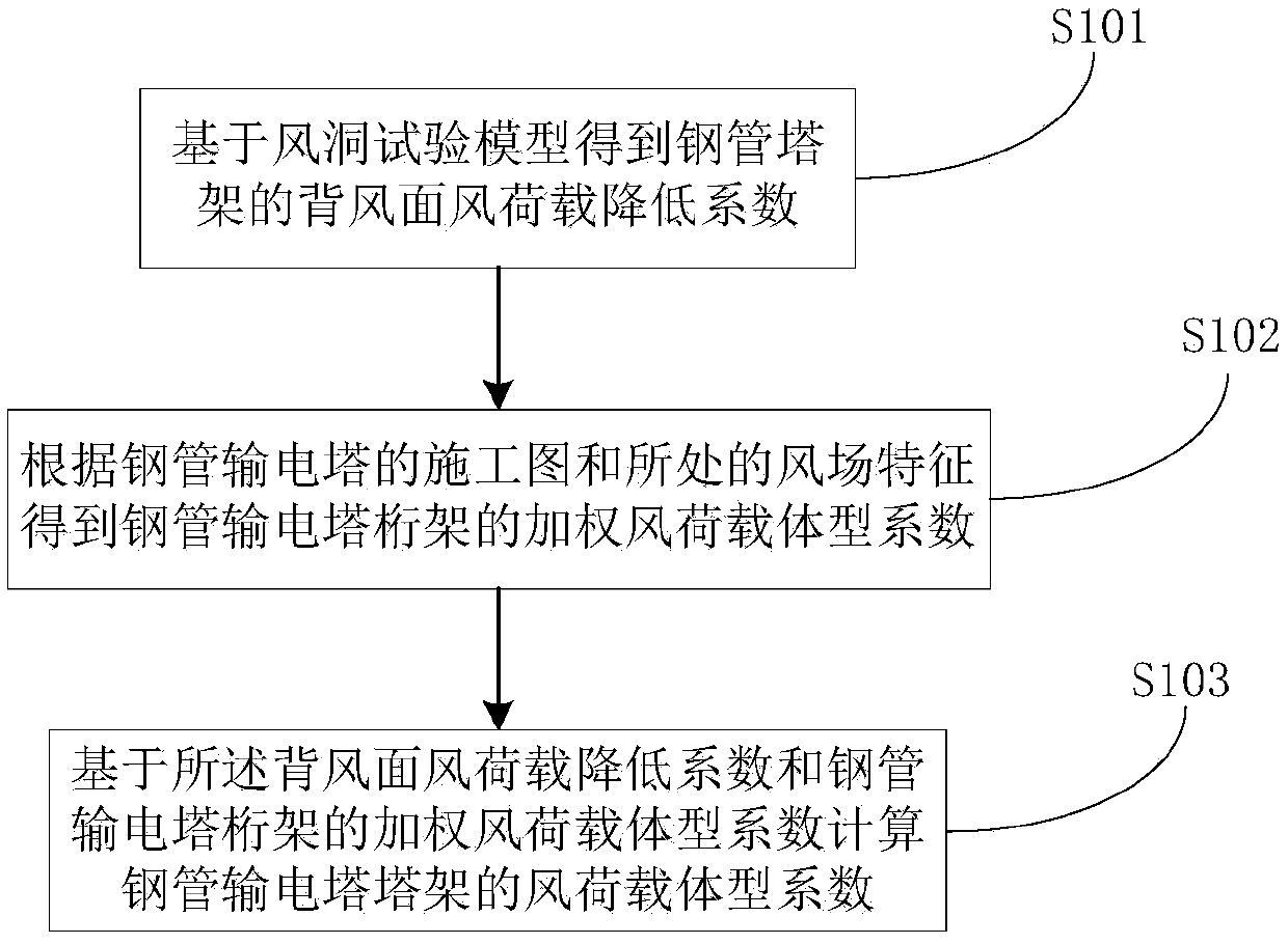
[0065] figure 1 It is a flow chart of a method for confirming the wind load shape coefficient of a steel pipe transmission tower frame, such as figure 1 described, including the following steps:

[0066] Step S101, obtaining the wind load reduction factor on the leeward side of the steel pipe tower based on the pre-built wind tunnel test model;

[0067] Step S102, obtaining the weighted wind load shape coefficient of the steel pipe transmission tower truss according to the construction drawing of the steel pipe transmission tower and the characteristics of the wind field;

[0068] Step S103, based on the wind load reduction coefficient on the leeward side and the weighted wind load form coefficient of the steel pipe transmission tower truss, determine the wind load form coefficient of the steel pipe transmission tower truss.

[0069] Step S101 specifically includes:

[0070] In the pre-established wind tunnel test model, the windward side of the steel pipe tower is connecte...

Embodiment 2

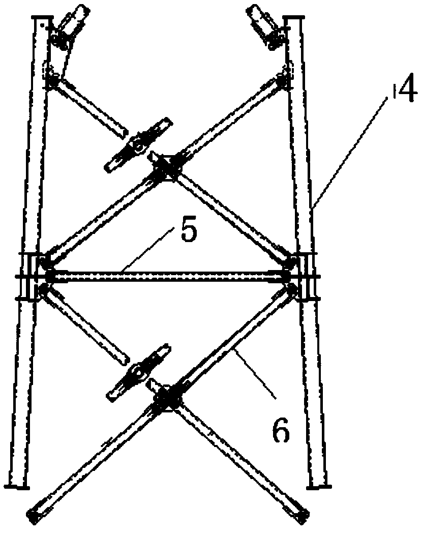
[0113] Taking the steel pipe transmission tower of a 500kV transmission line in a mountainous area as an example, as image 3 As shown, the specifications of the tower body main material, transverse section horizontal member and tower body oblique material in this section are Φ356×10, Φ168×5 and Φ219×5, respectively. The roughness category of the wind field where the tower is located is Class B, the design wind speed V=30m / s, and the attached image 3 The centroid of the segment shown is at a height z=20 m from the ground.

[0114] Step (1) Determine the wind load reduction factor on the leeward side of the steel pipe tower

[0115] Design the full-scale wind tunnel test model of the steel pipe transmission tower section according to the construction drawing of the steel pipe transmission tower structure, connect the windward side or the leeward side of the steel pipe tower to the high-frequency force measuring balance separately, and install the other side on the sliding gui...


PUM


Abstract

The invention discloses a confirmation method and device for a wind load form factor of a steel pipe power transmission tower structure. The method comprises the steps of obtaining a leeside wind loadreduction factor of a steel pipe tower structure based on a pre-established wind tunnel test model; obtaining a weighted wind load form factor of a steel pipe power transmission tower truss accordingto a construction drawing of a steel pipe power transmission tower and a wind field feature; and determining the wind load form factor of the steel pipe power transmission tower structure according to the leeside wind load reduction factor and the weighted wind load form factor of the steel pipe power transmission tower truss. Steel pipe leeside shielding effect, fluctuating wind effect and steelpipe spatial position influences are taken into consideration, and the precision of confirming the wind load form factor of the steel pipe power transmission tower is improved.

Description

technical field [0001] The invention relates to the field of design load calculation of transmission lines, in particular to a method and device for confirming the wind load type coefficient of a steel pipe transmission tower frame. Background technique [0002] The wind load effect of steel pipe transmission tower belongs to the category of flow around a typical blunt body, often accompanied by phenomena such as airflow separation, reattachment and vortex shedding, and its Reynolds number effect is more complicated. The Reynolds number is one of the key parameters for the wind load calculation of the steel pipe transmission tower. The wind load shape coefficient of the steel pipe segment will change with the change of the Reynolds number, so that the steel pipe transmission tower structure will show different response characteristics under different incoming wind speeds. , how to accurately consider the impact of this change is the key problem to be solved in the wind-resis...

Claims


Application Information

Patent Timeline
Patent Type & Authority Applications(China)
IPC IPC(8): G06F17/50
CPCG06F30/20
Inventor 杨风利李正张宏杰黄国王飞
Owner CHINA ELECTRIC POWER RES INST
Why Eureka
Try Eureka