Smart urban subway ticketing device for hearing impaired passengers
A hearing-impaired, intelligent technology, applied in ticketing equipment, ticket printing machines, instruments, etc., can solve problems such as missing transfer stations or destination stations, hearing-impaired passengers unable to accurately obtain stop information, etc.
- Summary
- Abstract
- Description
- Claims
- Application Information
AI Technical Summary
Problems solved by technology
Method used
Image
Examples
Embodiment 1
[0036] like figure 1 As shown, the structural block diagram of the intelligent urban railway ticket device suitable for hearing-impaired passengers of the present invention has a reminder function while having the existing ticket function. The existing ticket functions include ticket purchase, recharge and ticket inspection. figure 1 The shown intelligent urban railway ticket equipment suitable for hearing-impaired passengers includes a microprocessor 2, a communication unit 1, a memory 5, a vibrator 4, a display screen 3 and a power supply assembly. The communication unit 1 , the memory 5 , the vibrator 4 and the display screen 3 are respectively connected with the microprocessor 2 . The power supply component provides power supply for the microprocessor 2 , the communication unit 1 , the memory 5 , the vibrator 4 and the display screen 3 . The microprocessor 2 stores the information from the ticketing system acquired by the communication unit 1 in the memory 5, and the micr...
Embodiment 2
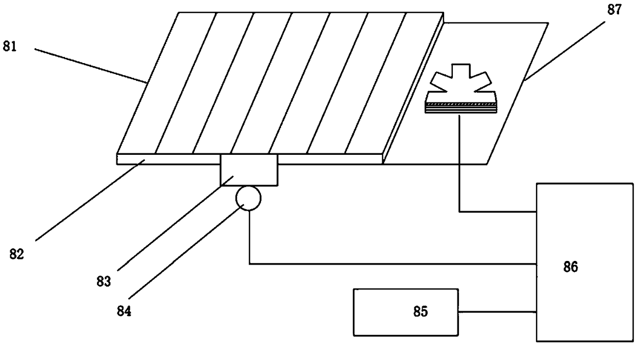
[0043] The difference between this embodiment and the above embodiments is that the power supply equipment is a solar collector 8 . The solar energy collection device is arranged on the outside of the urban railway carriage to collect solar energy. While ensuring the power supply of the intelligent urban railway ticket equipment suitable for hearing-impaired passengers, it does not increase the power burden of the urban railway carriages.
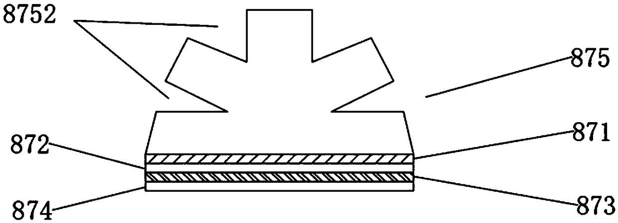
[0044] Due to the diversity of directions of urban railway lines, the solar collector 8 needs to flexibly adjust the direction function to ensure maximum solar energy acquisition. like figure 2 Shown is a schematic structural view of a solar energy collection device 8 provided in this embodiment. The solar collection device includes a solar tube 81 , an adjustment device 83 , a position module 85 , a processor 86 and a guide device 87 . The solar tube 81 is used to collect solar energy; the guide device 87 and the position module 85 are...
Embodiment 3
[0050] like Figure 4A and Figure 4B As shown, the difference between this embodiment and the above-mentioned embodiments is that the number of light-guiding surfaces on the refraction layer 875 of this embodiment is set to five, including a first light-guiding surface 8753, two second light-guiding surfaces 8754 and The two third light-introduction surfaces 8755 and the five light-introduction surfaces are arranged in a semicircle, which is beneficial to fully collect solar energy.
[0051] like Figure 4A As shown, when the sun directly shines on the first light-guiding surface 8753 located in the middle part of the section of the guide device 87, the incident light of the sun is perpendicular to the first light-guiding surface 8753 and enters the refraction layer 875, and then irradiates on the heat-absorbing layer after entering the refraction layer 875 871 on the position corresponding to the first light-guiding surface 8753; on the heat-absorbing layer 871 opposite to...
PUM
 Abstract
Description
Claims
Application Information
 - R&D
- Intellectual Property
- Life Sciences
- Materials
- Tech Scout
- Unparalleled Data Quality
- Higher Quality Content
- 60% Fewer Hallucinations
Browse by: Latest US Patents, China's latest patents, Technical Efficacy Thesaurus, Application Domain, Technology Topic, Popular Technical Reports.
© 2025 PatSnap. All rights reserved.Legal|Privacy policy|Modern Slavery Act Transparency Statement|Sitemap|About US| Contact US: help@patsnap.com


