A Hybrid Excitation Flux Switching Motor with Claw Pole Bypass Structure in the Stator
A magnetic flux switching motor and mixed excitation technology, which is applied in the direction of synchronous machines, electromechanical devices, electrical components, etc., can solve problems such as adverse effects on motor performance, improve independent design margins, reduce resistance and copper consumption, and improve motor efficiency Effect
- Summary
- Abstract
- Description
- Claims
- Application Information
AI Technical Summary
Problems solved by technology
Method used
Image
Examples
Embodiment 1
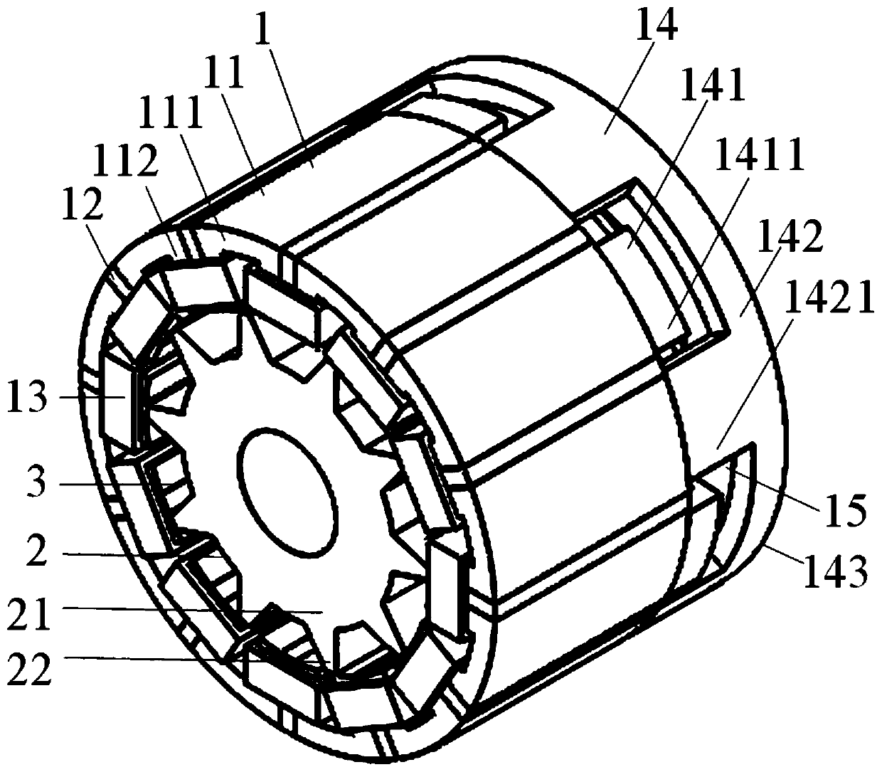
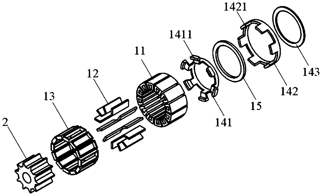
[0043] Such as figure 1 , 2 , 3, 4, 5, and 6.
[0044] A hybrid excitation flux switching motor with a claw pole bypass structure on the stator, comprising a stator 1 with a claw pole bypass structure, a rotor 2 with salient poles coaxially arranged in the stator 1, the An air gap 3 is provided between the stator 1 and the rotor 2;
[0045] The stator 1 is composed of a number of U-shaped stator cores 11 arranged at equal intervals along the circumference with the opening direction radially facing the center of the circle, permanent magnets 12 embedded between adjacent U-shaped stator core teeth 112, and wound in the form of concentrated winding. The armature winding 13 on the adjacent U-shaped stator core teeth 112, the claw pole bypass assembly 14 and the excitation coil 15 are formed. The U-shaped stator core 11 is composed of a stator core yoke 111 and a stator core tooth 112; the permanent magnets 12 are magnetized tangentially along the circumference, and the adjacent...
Embodiment 2
[0050] Such as figure 1 , 2 shown
[0051] A hybrid excitation flux switching motor with a claw pole bypass structure in the stator as described in Embodiment 1, the difference is that the claw pole bypass assembly 14 consists of separated U-shaped stator cores with the same magnetic pole polarity The yoke 111 extends from one side of the axial direction to an axial primary pole core ring 141 with an axial Z-shaped claw pole 1411, and a separate U-shaped stator core yoke 111 with the same magnetic pole polarity is aligned in the axial direction. An axial-type secondary pole core ring 142 with axial straight-toothed claw poles 1421 extends from the side, and is arranged on the same axial side of the primary pole core ring 141 and the secondary pole core ring 142 to connect them together in the radial direction. Consists of a radial cover core ring 143;
[0052] The axial lengths of the primary pole core ring 141 and the secondary pole core ring 142 are equal;
[0053] The r...
Embodiment 3
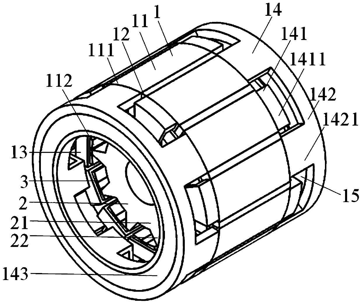
[0057] Such as image 3 , 4 shown
[0058] As described in Embodiment 2, a hybrid excitation flux switching motor with a claw pole bypass structure in the stator, the difference is that it can also be designed to set the claw pole bypasses on both sides of the U-shaped stator core yoke 111 axially. The bilateral bypass excitation structure of the road assembly 14, the structure of the claw pole bypass assembly 14 on each side is the same as that described in Embodiment 2;
[0059] The claw poles of the primary pole core ring 141 of the claw pole bypass assembly 14 on both sides are respectively connected to U-shaped stator core yokes 111 with different magnetic pole polarities along the axial direction in space, that is to say, the claw poles on one side are The axial Z-shaped claw poles 1411 of the primary pole core ring 141 of the road assembly 14 are respectively connected with the axial Z-shaped claw poles 1411 of the primary pole core ring 141 of the claw pole bypass as...
PUM
 Abstract
Description
Claims
Application Information
 - R&D
- Intellectual Property
- Life Sciences
- Materials
- Tech Scout
- Unparalleled Data Quality
- Higher Quality Content
- 60% Fewer Hallucinations
Browse by: Latest US Patents, China's latest patents, Technical Efficacy Thesaurus, Application Domain, Technology Topic, Popular Technical Reports.
© 2025 PatSnap. All rights reserved.Legal|Privacy policy|Modern Slavery Act Transparency Statement|Sitemap|About US| Contact US: help@patsnap.com


