Experimental decoupling device to realize physical separation of centrifugal fan excitation characteristics

A centrifugal fan, physical separation technology, applied in mechanical equipment, machine/engine, pump control, etc., can solve the problems of inability to reduce vibration and noise, difficulty in quantitative identification of excitation sources, inability to separate excitation sources, etc., to reduce vibration. Effect

Active Publication Date: 2016-10-05
SHANGHAI CSIC SHIP PROPULSION EQUIP CO LTD
View PDF7 Cites 0 Cited by
  • Summary
  • Abstract
  • Description
  • Claims
  • Application Information

AI Technical Summary

Problems solved by technology

[0006] (1) The vibration and noise generated by airflow excitation, mechanical excitation and electromagnetic excitation are coupled with each other. The vibration and noise response of the electric centrifugal fan is the aliasing effect of each excitation source, and the separation of excitation sources cannot be realized. It is very difficult, and it is impossible to achieve a directional vibration and noise reduction design for different excitation characteristics of centrifugal fans;
[0007] (2) The existing electric centrifugal fan cannot realize the adjustment of the relative position of the impeller and the volute, and cannot complete the experimental research on the influence of the relative position change of the impeller and the volute of the electric centrifugal fan on the vibration and noise of the electric centrifugal fan

Method used


Image

  • Experimental decoupling device to realize physical separation of centrifugal fan excitation characteristics
  • Experimental decoupling device to realize physical separation of centrifugal fan excitation characteristics
  • Experimental decoupling device to realize physical separation of centrifugal fan excitation characteristics

Examples


Embodiment Construction

[0026] The present invention will be further described below in conjunction with the accompanying drawings and embodiments.

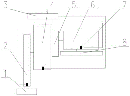
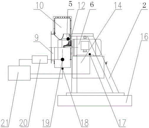
[0027] Such as figure 1 As shown, a test decoupling device for realizing the physical separation of centrifugal fan excitation characteristics is mainly composed of a decoupling system, a support system, a fan system, a drive system, and a test system.

[0028] The decoupling system is composed of a separate decoupling bracket 2 specially designed for centrifugal fans; the support system is composed of a decoupling system support base 1 and a drive system support base 8. The two support bases are independent of each other and can be rigid support or elastic according to the purpose of the test. Support; fan system 4 is composed of centrifugal fan related components and impeller 5; drive system is composed of drive motor 6, the speed of which is adjustable; test system is composed of signal acquisition and data analysis device 3 and sensor 7. The fan s...


PUM


Abstract

The invention relates to a test decoupling device for realizing the physical separation of excitation characteristics of a centrifugal fan. The volute is fixedly connected with a separation decoupling bracket 2 through a connecting disk, the separation decoupling bracket 2 is fixed on the support base of the decoupling system, and the impeller is directly installed. On the motor shaft of the driving motor, the machine feet of the driving motor are installed on the supporting base of the driving system. The supporting base 1 of the decoupling system and the supporting base of the driving system are independent of each other to realize the physical separation between the volute and the rotor of the motor. Acceleration sensors are arranged at the foot of the machine, which are used to measure the shaft frequency and harmonic frequency of the shaft system composed of the motor rotor and impeller, and the electromagnetic excitation frequency of the motor; acceleration sensors and dynamic The pressure sensor is used to measure the blade frequency and its harmonic frequency and the fan broadband air flow excitation, and the acceleration sensor and the dynamic pressure sensor are respectively connected to the data analysis device.

Description

technical field [0001] The invention relates to a centrifugal fan test device, in particular to a test decoupling device capable of realizing the physical separation of centrifugal fan airflow excitation, mechanical excitation and electromagnetic excitation. Background technique [0002] The centrifugal fan is a liquid machine that converts the mechanical energy of the prime mover into the pressure energy and kinetic energy of the transported gas. Reducing its vibration and air noise is not only conducive to reducing the transmission vibration of the hull structure, but also reducing the underwater radiation noise of the hull. The working environment and living environment of the crew have been improved. [0003] The vibration and noise of electric centrifugal fans are mainly caused by airflow excitation, mechanical excitation and electromagnetic excitation. Fluid vibration noise is the airflow excitation generated by the impeller of the electric centrifugal fan passing thr...

Claims


Application Information

Patent Timeline
Patent Type & Authority Patents(China)
IPC IPC(8): F04D27/00
Inventor 章艺李国平王强周璞柳瑞锋
Owner SHANGHAI CSIC SHIP PROPULSION EQUIP CO LTD
Why Eureka
Try Eureka