
Power detection circuit and method

A technology of power detection and electrical detection, which is applied in the direction of electronic switches, electrical components, pulse technology, etc., and can solve problems such as low detection accuracy, no power-down detection function, and large power consumption.

Active Publication Date: 2018-10-12
VERISILICON MICROELECTRONICS SHANGHAI
View PDF11 Cites 26 Cited by
  • Summary
  • Abstract
  • Description
  • Claims
  • Application Information

AI Technical Summary

Problems solved by technology

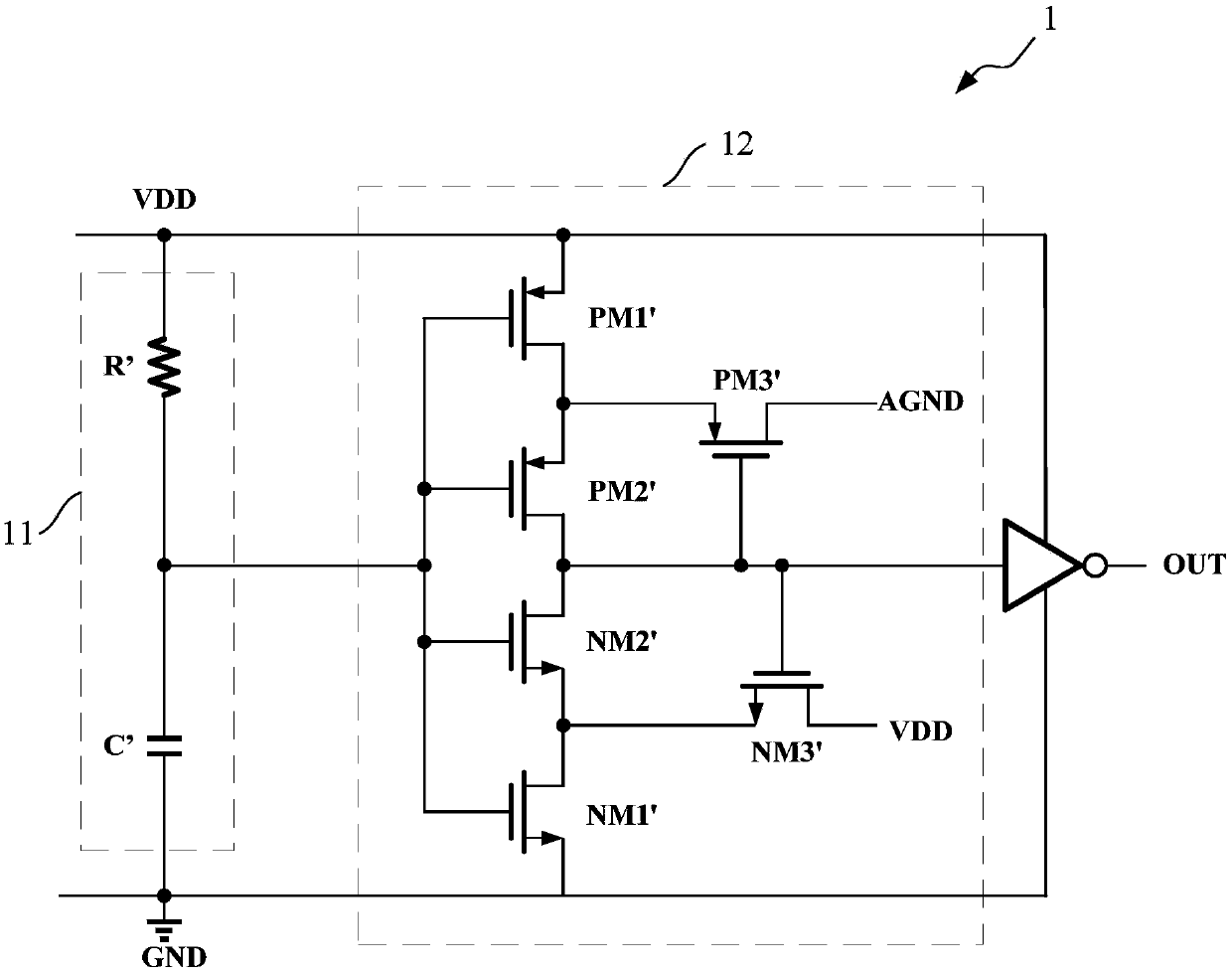
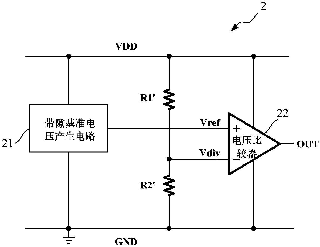
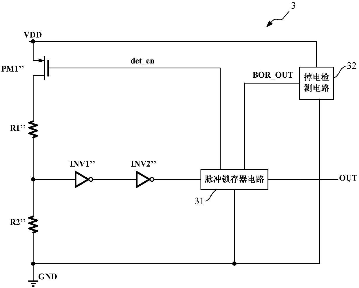
[0008] In view of the shortcomings of the prior art described above, the purpose of the present invention is to provide a power detection circuit and method for solving the problems of low detection accuracy, lack of power-down detection function, and power consumption in the power-on reset circuit in the prior art. major issues

Method used


Image

  • Power detection circuit and method
  • Power detection circuit and method
  • Power detection circuit and method

Examples


Embodiment Construction

[0095] Embodiments of the present invention are described below through specific examples, and those skilled in the art can easily understand other advantages and effects of the present invention from the content disclosed in this specification. The present invention can also be implemented or applied through other different specific implementation modes, and various modifications or changes can be made to the details in this specification based on different viewpoints and applications without departing from the spirit of the present invention.

[0096] see Figure 4 ~ Figure 9 . It should be noted that the diagrams provided in this embodiment are only schematically illustrating the basic idea of ​​the present invention, and only the components related to the present invention are shown in the diagrams rather than the number, shape and shape of the components in actual implementation. Dimensional drawing, the type, quantity and proportion of each component can be changed arbi...


PUM


Abstract

The invention provides a power detection circuit and method. The power detection circuit comprises a power supply switching module which is switched on or switched off according to power-on or brown-out condition; a voltage division sampling module for sampling a power supply voltage; a voltage comparison module for carrying out power-on detection; a brown-out detection module for carrying out brown-out detection; and a pulse latching module for latching a voltage rising edge transmitted by the voltage comparison module and a low level transmitted by the brown-out detection module. The methodcomprises the steps of switching on the power supply voltage, carrying out voltage division sampling on the power supply voltage and carrying out power-on detection on a signal obtained through voltage division sampling; carrying out power-on detection on the power supply voltage; outputting a first logic level if the power-on is finished, and carrying out delayed output to ensure that a system works stably; and outputting a second logic level if the brown-out occurs. The power detection circuit and method have a power-on detection function; after the power-on is finished, no power consumptionexists; and the detection precision of the power detection circuit and method is far higher than that of the prior art.

Description

technical field [0001] The invention relates to the field of analog integrated circuits, in particular to a power supply detection circuit and method. Background technique [0002] In an integrated circuit system, digital circuits located on a chip, such as control units and registers, will be in an uncertain state during power-on. Therefore, a circuit is needed to initialize and reset these uncertain states to ensure that the entire system of the chip can work normally. Usually, we use a power-on reset circuit (POR: Power-on-Reset) to achieve this function: before the power supply voltage is at the voltage threshold for the normal operation of the digital circuit, the POR set signal makes the digital circuit in a fixed initialization State; after the power supply voltage rises to the threshold voltage, the POR set signal is released, and the digital circuit can work normally. [0003] A reliable power-on reset circuit (POR) needs to meet the following requirements: 1) The...

Claims


Application Information

Patent Timeline
Patent Type & Authority Applications(China)
IPC IPC(8): H03K17/22G06F1/24
CPCH03K17/223G06F1/24
Inventor 蔡语昕丁川钱润发
Owner VERISILICON MICROELECTRONICS SHANGHAI
Learn More