
Cylinder-driven robot joint device

A technology driven by robot joints and cylinders, used in passive exercise equipment, sports accessories, gymnastics equipment, etc., can solve the problems of high price, difficult and low-cost design, and large size of dynamic torque sensors, and achieve obvious flexibility and safety. , taking into account the quality and overcoming the effect of layout limitations

Active Publication Date: 2018-10-16
HUBEI UNIV OF TECH
View PDF13 Cites 0 Cited by
  • Summary
  • Abstract
  • Description
  • Claims
  • Application Information

AI Technical Summary

Problems solved by technology

[0003] At present, there are two main solutions to solve the dynamic torque feedback of rehabilitation robot joints. One is to install dynamic torque sensors at the joints of rehabilitation robots, which have high precision and good real-time performance, but dynamic torque sensors are expensive, large in size and heavy in weight. , it is difficult to achieve a compact and lightweight low-cost design; the other is to install a six-axis force (torque) sensor at the corresponding position of the rehabilitation robot, and then decompose the force to each joint. Similarly, the six-axis force (torque) sensor is also facing and Similar issues with dynamic torque sensors

Method used


Image

  • Cylinder-driven robot joint device
  • Cylinder-driven robot joint device

Examples


Embodiment Construction

[0018] The technical solutions in the embodiments of the present invention will be clearly and completely described below in conjunction with the accompanying drawings in the embodiments of the present invention. Obviously, the described embodiments are only a part of the embodiments of the present invention, rather than all the embodiments. Based on the embodiments of the present invention, all other embodiments obtained by a person of ordinary skill in the art fall within the protection scope of the present invention.

[0019] In order to facilitate the understanding of the above-mentioned technical solutions of the present invention, the above-mentioned technical solutions of the present invention will be described in detail below through specific usage.

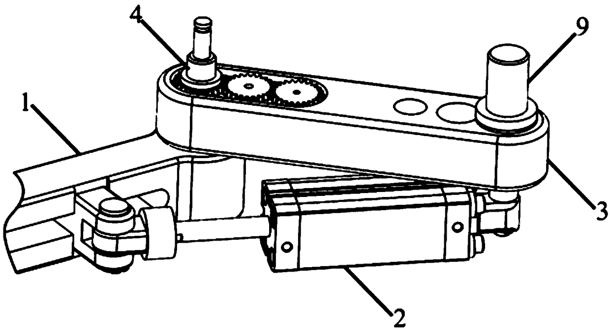
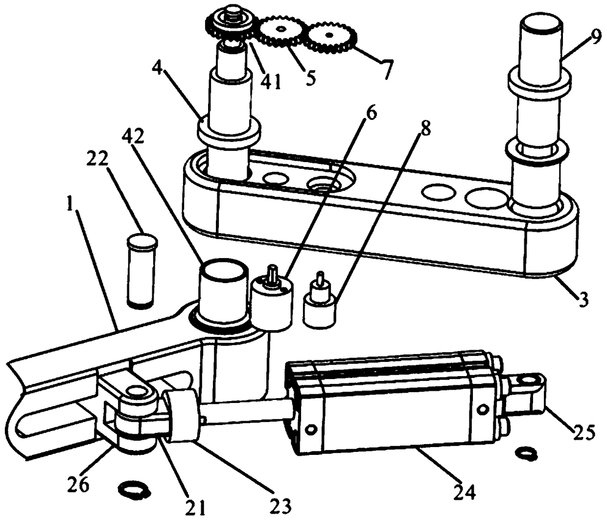
[0020] Such as figure 1 with figure 2 As shown, a cylinder-driven robot joint device of the present invention includes a base beam 1, a cylinder assembly 2, a shoulder joint rotating arm 3, a first connecting shaft 4, an incr...


PUM


Abstract

The invention relates to the field of medical rehabilitation machinery, in particular to a cylinder-driven robot joint device. A first connecting rotating shaft is installed in a bore of a base crossbeam, a first rotating shaft gear is fixed to the first connecting rotating shaft, and the first connecting rotating shaft is connected to a shoulder joint rotating arm through a self-lubricating bearing. The first rotating shaft gear meshes with an incremental encoder gear, and the incremental encoder gear is connected with an incremental encoder. The incremental encoder gear meshes with a Hall sensor gear, and the Hall sensor gear is connected with a Hall sensor. The incremental encoder and the Hall sensor are mounted on the shoulder joint arm. The cylinder-driven robot joint device has thecharacteristics of good safety performance, high controllability and the like.

Description

Technical field [0001] The invention relates to the field of medical rehabilitation machinery, in particular to a robot joint device driven by a cylinder. Background technique [0002] The upper limb rehabilitation training robot is produced by combining the field of robotics with the field of rehabilitation medicine. It is a new technology that supplements or replaces professional physicians to complete the rehabilitation of human upper limbs. Its emergence opens up a new way for the rehabilitation of upper limb hemiplegia patients. The road has made up for the lack of clinical treatment for patients with hemiplegia. The treatment method of the rehabilitation training robot is to connect the affected limb with the robot. The patient's limbs are driven by the robot to complete various actions to stimulate the nerve control system of the human upper limb joints and muscles, so as to achieve the purpose of restoring the patient's limb motor function. This method reduces the depend...

Claims


Application Information

Patent Timeline
IPC IPC(8): A61H1/02A63B21/00
CPCA61H1/02A61H2201/1238A61H2201/5058A61H2201/5061A61H2201/5071A63B21/00178A63B21/00181
Inventor 苏晨李佳璐李建伍赛
Owner HUBEI UNIV OF TECH
Learn More