Optical Head Apparatus and Optical Information Apparatus

a head apparatus and head technology, applied in the direction of data recording, instruments, disposition/mounting of heads, etc., can solve the problems of reducing the size affecting the miniaturization of the optical head apparatus, and unable to obtain sufficient driving force, etc., to achieve stable focusing control capability

Active Publication Date: 2008-07-03
PANASONIC CORP
View PDF3 Cites 10 Cited by
  • Summary
  • Abstract
  • Description
  • Claims
  • Application Information

AI Technical Summary

Benefits of technology

[0018]Accordingly, in the optical head apparatus provided with a plurality of objective lenses to realize the compatible-type optical information apparatus which is capable of conducting recording and reproducing onto and from a plurality of optical discs having different recording densities, a stable focusing control capability can be realized for optical discs having different recording densities.

Problems solved by technology

However, the first prior art has the problem that because the two objective lenses are provided, the space between the objective lenses 64 and 69 cannot be reduced, which consequently hinders the miniaturization of the optical head apparatus.
This causes a problem that the driving force cannot be obtained sufficiently.
For this reason, there has been the problem that the size of the optical head apparatus becomes considerably larger in a direction perpendicular to an optical disc placed in the optical head apparatus.
Even if this technique is combined with the first prior art, there still remains a problem.
As a result, this causes the problem that the sufficient driving force cannot be obtained.

Method used


Image

  • Optical Head Apparatus and Optical Information Apparatus
  • Optical Head Apparatus and Optical Information Apparatus
  • Optical Head Apparatus and Optical Information Apparatus

Examples


first embodiment

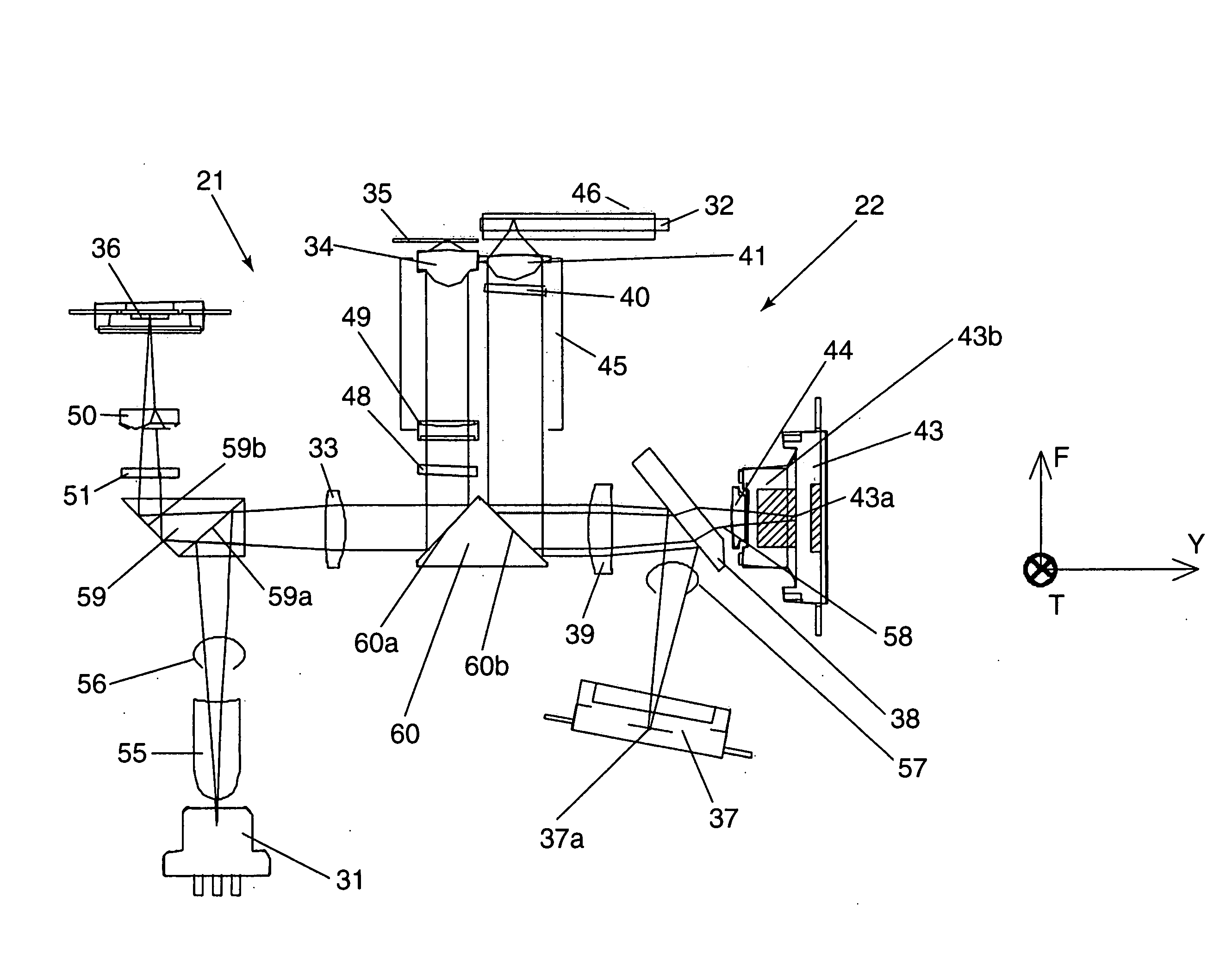
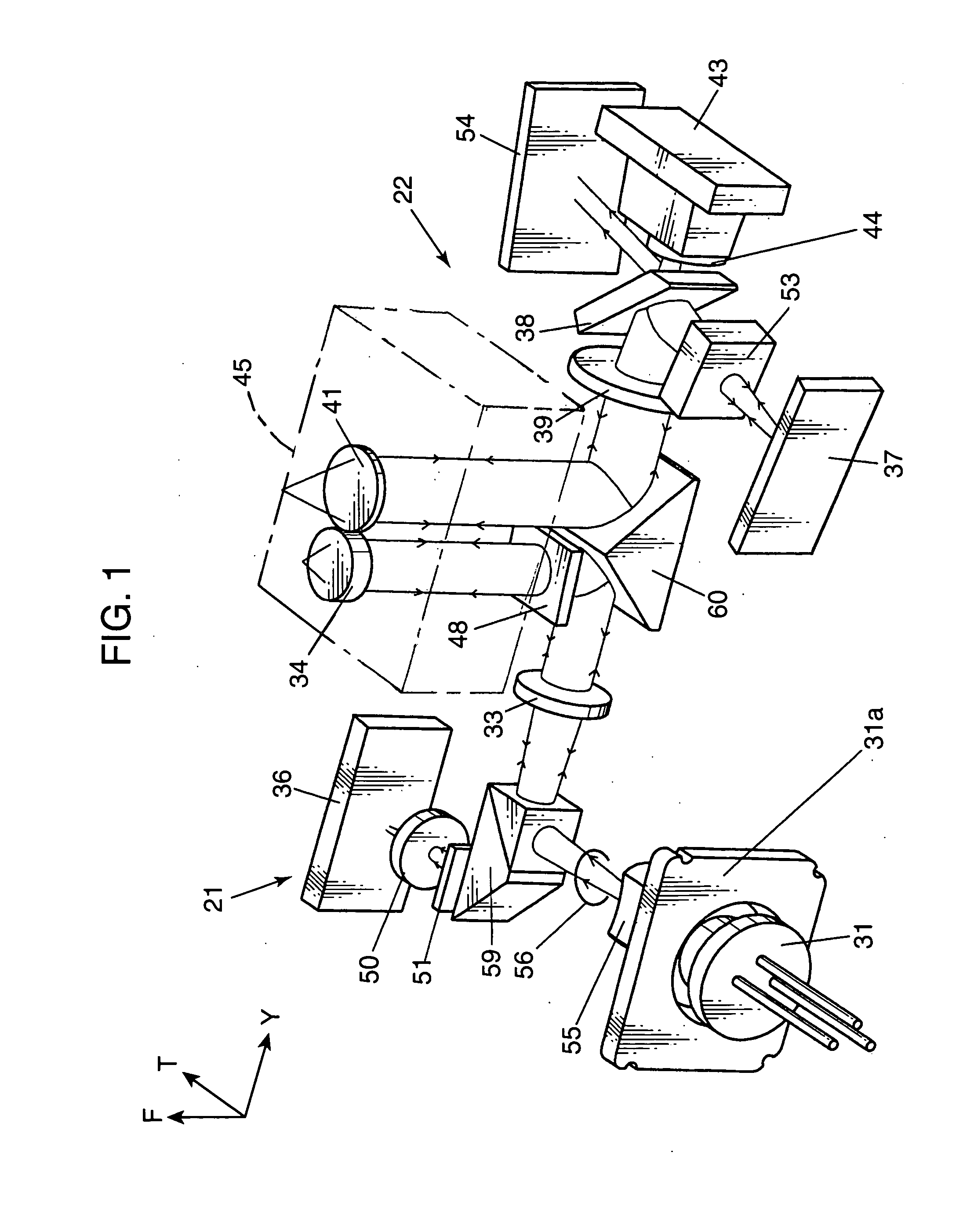
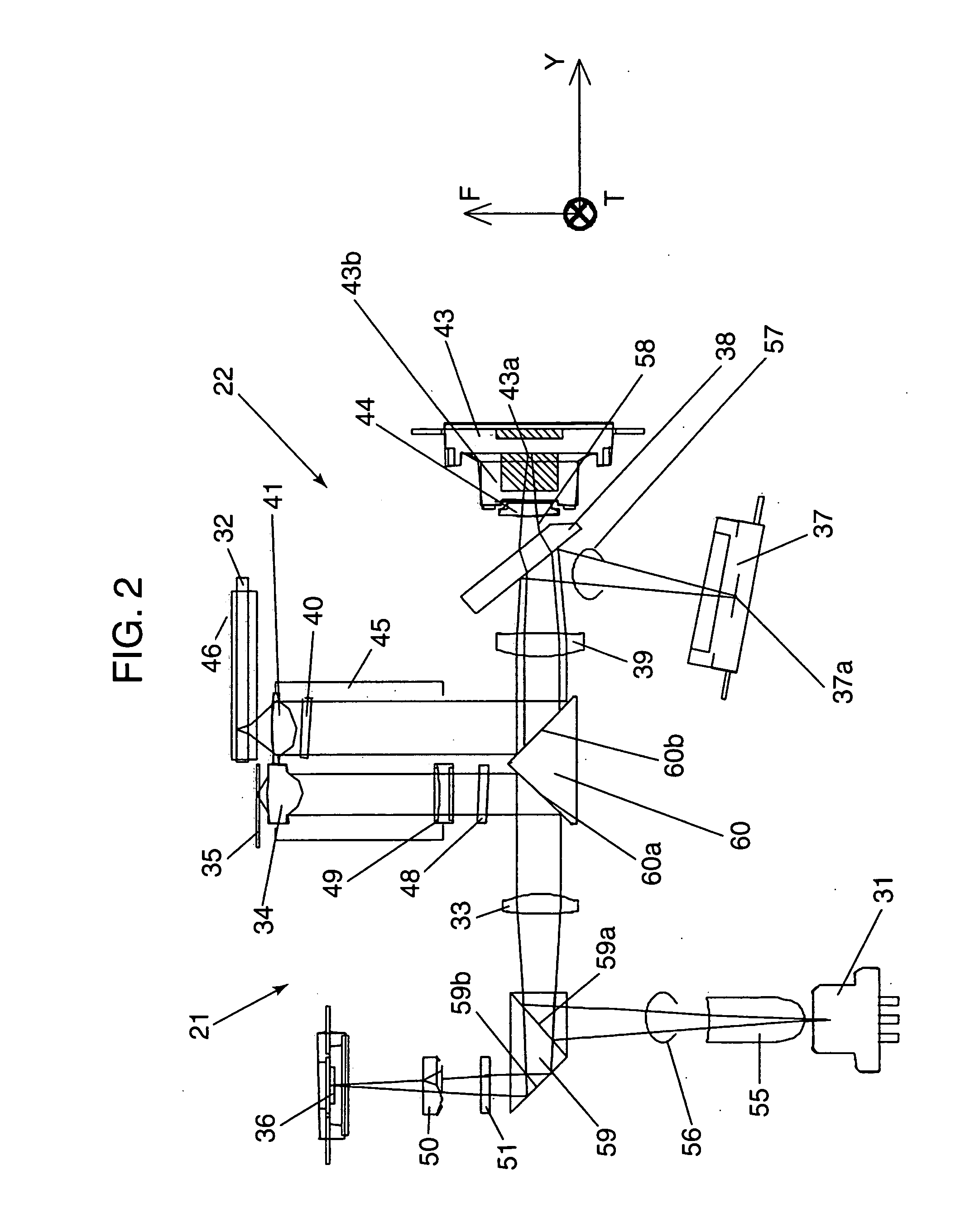
[0037]FIG. 1 is a perspective view showing a main part of an optical head apparatus according to a first embodiment of the present invention. FIG. 2 is a diagrammatic general side view showing the optical head apparatus according to the first embodiment of the present invention. FIG. 3 is a perspective view showing a configuration of an objective lens actuator according to the first embodiment of the present invention. FIG. 4 is an exploded perspective view showing the configuration of the objective lens actuator according to the first embodiment of the present invention.

[0038]In FIGS. 1 to 3, T, F, and Y respectively indicate a tracking direction (T-direction), a focusing direction (F-direction), and a tangential direction (Y-direction) to an optical disc. The tracking direction is substantially perpendicular to optical axes of objective lenses 34 and 41 and substantially perpendicular to a tangential direction to a track groove of optical discs 32, 35, and 46, namely, in a directi...

second embodiment

[0108]FIG. 12 schematically shows an optical information apparatus 167 according to an embodiment of the present invention. The optical head apparatus 155 described in the first embodiment is provided in the optical information apparatus 167. In FIG. 12, the optical disc 35 (or the optical disc 32 or 46, hereinafter the same as the above) is mounted on a turn table 162 to be held by the turn table 162 and a clamper 163, and rotated by a motor 164. The optical head apparatus 155 is moved by a driving device 151 of the optical head apparatus to a track in the optical disc 35 where the desired information exists.

[0109]Then, the optical head apparatus 155 responds to a positional relationship with the optical head disc 35, and sends the focusing error (an error in a focusing point) signal or the tracking error signal to an electric circuit 153. The electric circuit 153 responds to the signal and sends a signal for slightly moving the objective lens to the optical head apparatus 155. In ...

third embodiment

[0111]FIG. 13 shows an appearance of the computer 100 provided with the optical information apparatus 167 described in the second embodiment.

[0112]The computer 100 is provided with the optical information apparatus 167, an input device 65, such as a keyboard, a mouse, or a touch screen for inputting the information, a calculating device 64, such as a central processing unit (CPU) for operating a calculation based on the information inputted by the input device 65 or the information read from the optical information apparatus 167, and an output device 61, such as a Braun tube, a liquid crystal display device, or a printer for displaying the information such as a result calculated by the calculating device 64.


PUM

PropertyMeasurementUnit
wavelengthaaaaaaaaaa
thicknessaaaaaaaaaa
angleaaaaaaaaaa

Abstract

An optical head apparatus is made to be downsized while obtaining an sufficient driving force of an objective lens actuator. The optical head apparatus includes a first optical system including a first objective lens for focusing a light beam upon an optical disc; a second optical system including a second objective lens for focusing a light beam upon an optical disc having an information recording density smaller than the optical disc which the first optical system irradiates upon, the second objective lens having a numerical aperture smaller than the first objective lens; and an up-orienting prism including a first reflecting surface for deflecting a light beam to an optical axis of the first objective lens in the first optical system, and a second reflecting surface for deflecting a light beam to an optical axis of the second objective lens in the second optical system.

Description

TECHNICAL FIELD[0001]The present invention relates to an optical information apparatus which conducts reproducing of information from an information recording medium such as an optical disc, and recording of information in a recording medium, and an optical head apparatus which conducts reproducing and recording of information in the optical information apparatus.BACKGROUND ART[0002]A digital versatile disc (DVD) is known as an optical disc capable of recording a large volume of data, since it can record digital information about six times as much as a compact disc (CD). Recently, as an information amount to be recorded in an optical disc increases, an optical disc having a large capacity is required. In order to make an optical disc have a large capacity, it becomes necessary to increase the recording density of information by miniaturizing the optical spot to be defined by a ray of light irradiated onto the optical disc when the information is recorded on the optical disc and the ...

Claims


Application Information

Patent Timeline
Patent Type & Authority Applications(United States)
IPC IPC(8): G11B7/09G11B7/08G11B7/135G11B7/1359G11B7/1362
CPCG11B7/0908G11B7/0932G11B7/0933G11B7/0935G11B2007/0006G11B7/0956G11B7/1359G11B7/1362G11B7/0941
Inventor WAKABAYASHI, KANJIKOMMA, YOSHIAKITANAKA, TOSHIYASU
Owner PANASONIC CORP
Why Eureka
Try Eureka