Composite large-area crusher cavity

A crusher, large-area technology, applied in grain processing and other directions, can solve the problems of poor forming degree of crushed materials, reduce crushing efficiency, and affect crushing effect, etc., to strengthen crushing and trimming, improve crushing efficiency, and avoid chaos hit effect

Pending Publication Date: 2018-10-16
四川皇龙智能破碎技术股份有限公司
View PDF0 Cites 4 Cited by
  • Summary
  • Abstract
  • Description
  • Claims
  • Application Information

AI Technical Summary

Problems solved by technology

[0003] The existing crusher cavity does not fully consider the direction of the material when it is crushed. The material enters the crusher from the feed port, and the path in the crusher is random, and there is no disordered material in the crusher. The interior is flying around, which not only fails to achieve a good crushing effect, but also greatly reduces the crushing efficiency. Many materials may bounce inside the crusher for a long time before they are completely crushed and discharged from the crusher, so that the shape of the crushed materials is relatively low. It also makes the hammer of the crushing roller wear faster, and the material powder produced by crushing does not consider the relationship between the speed of the material before crushing and the crushing, resulting in a slow feeding speed of the material, and it is impossible to ensure the quality of the material. The crushing speed greatly affects the crushing effect; and when the traditional crusher crushes the material, the powder produced by the crushing is more, especially the excessive powder inside the crusher is caused by the regular operation of the crusher. Inconvenient to use and subsequent cleaning

Method used


Image

  • Composite large-area crusher cavity
  • Composite large-area crusher cavity

Examples


Embodiment Construction

[0024] In order to make the purpose, technical solution and advantages of the present invention clearer, the present invention will be further elaborated below in conjunction with the accompanying drawings.

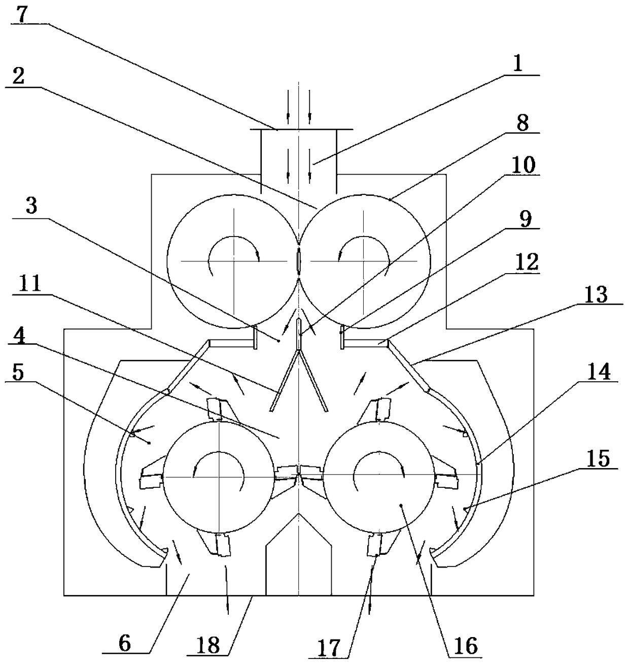
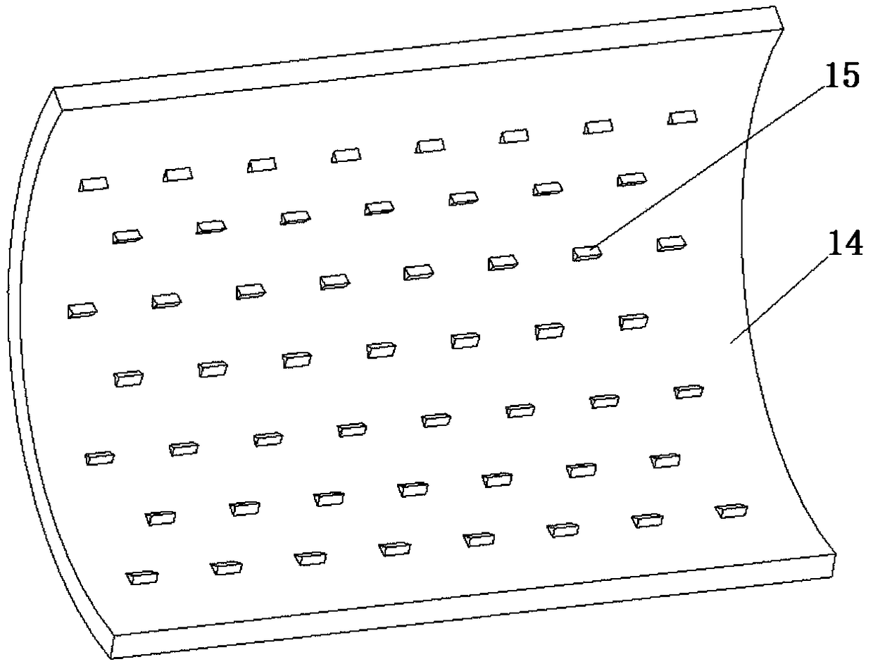
[0025] In this example, if figure 1 and 2 As shown, a composite large-area crusher cavity, the cavity includes a feed cavity 1, an acceleration cavity 2, a diversion cavity 3, a crushing cavity 4, a finishing cavity 5 and a discharge cavity 6 from top to bottom. , the accelerating chamber 2 includes two horizontally arranged accelerating rollers 8, the crushing chamber 4 includes two horizontally arranged crushing rollers 16, and the finishing chamber 5 is between the two crushing rollers 16 and the side wall of the chamber;

[0026] The top of the feeding chamber 1 is provided with a feeding port 7, and the bottom of the two accelerating rollers 8 is provided with a material guide plate 9, and the middle of the two material guide plates 9 is provided with a material dis...


PUM


Abstract

The invention discloses a composite large-area crusher cavity. The cavity comprises a feeding cavity, an accelerating cavity, a flow guiding cavity, a crushing cavity, finishing cavities and discharging cavities; the accelerating cavity comprises two accelerating rollers; the crushing cavity comprises two crushing rollers; the top of the feeding cavity is provided with a feeding port; the positions below the two accelerating rollers are each provided with a material guiding plate; the position between the two material guiding plates is provided with a material dividing device; first beat-backplates are fixed to the bottom ends of the two material guiding plates; the side walls of the two finishing cavities are each sequentially provided with a second beat-back plate and a third beat-backplate in sequence from top to bottom; a plurality of rows of anti-slip teeth are uniformly arranged on the third beat-back plates; and the discharging cavities with discharging ports are formed belowthe two crushing rollers correspondingly. The composite large-area crusher cavity is simple in structure, can be used for accelerating materials entering a crusher, and guides the materials to a preset path to be subjected to repeated large-area crushing, convenience is brought to crushing and finishing, the quality of crushed materials is increased, the powder amount is reduced, and the crushingefficiency is improved.

Description

technical field [0001] The invention belongs to the technical field of crushers, and in particular relates to a composite large-area crusher cavity. Background technique [0002] Crusher is a kind of equipment for crushing stones of different sizes. With the development of science and technology, there are more and more types of crushers. Crusher has been used in cement, building materials, coal and chemical industry and mineral processing in my country. It is widely used in the fine crushing and coarse crushing of various ores in the industrial sector. It has a large crushing ratio for crushing shale, coal, coal gangue, cinder, gypsum, salt mine emery and various brittle minerals below medium hardness. , small and uniform particle size, high output and long life. In the chemical industry and electric power sector, crushing and grinding machinery crushes and grinds raw materials, increases the surface area of ​​materials, and creates favorable conditions for shortening the che...

Claims


Application Information

Patent Timeline
Patent Type & Authority Applications(China)
IPC IPC(8): B02C13/02B02C13/20B02C13/286B02C13/282
CPCB02C13/02B02C13/20B02C13/282B02C13/286B02C2013/28663
Inventor 曹刚李寿海鲜红梅姜伟左明志吴杰
Owner 四川皇龙智能破碎技术股份有限公司
Why Eureka
Try Eureka