An electric propulsion deployment and thrust direction adjustment mechanism

An adjustment mechanism and electric propulsion technology, applied in the direction of space vehicle propulsion system devices, space vehicle guidance devices, etc., can solve the problems that electric thrusters cannot form a complete backup, low efficiency, and reduce the effective carrying capacity of spacecraft, etc., to achieve The effects of eliminating extra propellant consumption, reducing disturbance torque, and improving utilization efficiency

Active Publication Date: 2020-05-12
CHINA ACADEMY OF SPACE TECHNOLOGY
View PDF6 Cites 0 Cited by
  • Summary
  • Abstract
  • Description
  • Claims
  • Application Information

AI Technical Summary

Problems solved by technology

[0007] 1. The electric thruster cannot form a complete backup; when an electric thruster fails, the failure ignition strategy is used to work, and the propellant consumption will reach more than 1.5 times that of the normal ignition strategy, which reduces the effective carrying capacity of the spacecraft
[0008] 2. The actual installation position of the electric thruster is limited by the position of the center of mass of the spacecraft and the size of the back floor. Its efficiency in maintaining the north-south position is low, and the normal (north-south) acceleration can only account for about 0.5 times the total acceleration. lower utilization rate

Method used


Image

  • An electric propulsion deployment and thrust direction adjustment mechanism
  • An electric propulsion deployment and thrust direction adjustment mechanism
  • An electric propulsion deployment and thrust direction adjustment mechanism

Examples


Embodiment Construction

[0030] Below in conjunction with accompanying drawing and specific embodiment the present invention is described in further detail:

[0031] The invention proposes an electric propulsion deployment and thrust direction adjustment mechanism, which improves the backup capability of the electric thruster and reduces the propellant consumption under faulty ignition conditions; the invention can also simultaneously improve the efficiency of the electric thruster for maintaining the north-south position

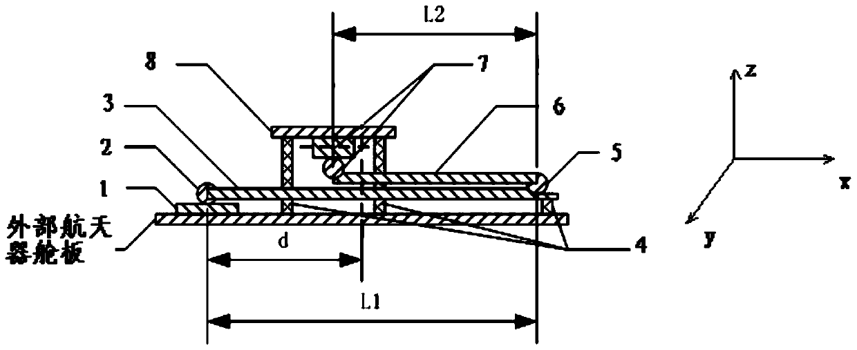
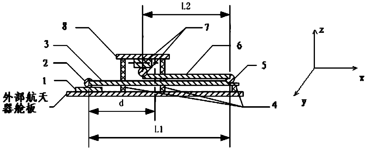
[0032] Such as figure 1Shown is a schematic structural diagram of the deployment and thrust direction adjustment mechanism. It can be seen from the figure that an electric propulsion deployment and thrust direction adjustment mechanism includes a mounting base plate 1, an elastic deployment joint 2, a first deployment arm 3, a locking mechanism 4, and a single degree of freedom Rotary joint 5, second deployment arm 6, double-degree-of-freedom rotary joint 7 and thruster mounting pl...


PUM


Abstract

The invention relates to an electric propulsion expansion and thrust direction adjustment mechanism, and relates to the field of spacecraft propulsion adjustment. The electric propulsion expansion andthrust direction adjustment mechanism comprises a mounting bottom plate, an elastic expansion joint, a first expansion arm, locking mechanisms, a single-degree-of-freedom revolute joint, a second expansion arm, a double-degree-of-freedom revolute joint and a thruster mounting plate. The axial end of the first expansion arm is fixedly connected with the upper surface of the mounting bottom plate through the elastic expansion joint, the locking mechanisms are fixedly mounted on the lower surface of the first expansion arm, and the single-degree-of-freedom revolute joint is fixedly mounted on the other axial end of the first expansion arm. The axial end of the second expansion arm is connected with the first expansion arm through the single-degree-of-freedom revolute joint, the double-degree-of-freedom revolute joint is fixedly mounted on the other axial end of the second expansion arm, and the double-degree-of-freedom revolute joint is fixedly connected with the lower bottom surface ofthe thruster mounting plate. According to the electric propulsion expansion and thrust direction adjustment mechanism, the backup capability of an electric thruster is improved, and the consumption ofa propellant under the condition of fault ignition is reduced; and at the same time, the efficiency of the electric thruster to maintain the north-south position can be improved.

Description

technical field [0001] The invention relates to the field of spacecraft propulsion adjustment, in particular to an electric propulsion deployment and thrust direction adjustment mechanism. Background technique [0002] The spacecraft in geostationary orbit (GEO) is in a static state relative to any observer on the earth, and it is widely used in communication, broadcasting, meteorology and other fields. In actual operation, due to perturbations such as the gravitational force of the sun and the moon, solar radiation pressure, and the non-spherical shape of the earth, geostationary orbit satellites do not exist in a static state, but drift in two directions: north-south (latitude) and east-west (longitude). According to application requirements, on-orbit position keeping should be implemented to limit the drift of the satellite in the north-south and east-west directions within a specified range. In most cases, for negative accelerations (south corrections), the optimum mome...

Claims


Application Information

Patent Timeline
Patent Type & Authority Patents(China)
IPC IPC(8): B64G1/40B64G1/24
CPCB64G1/24B64G1/40
Inventor 王珏王敏仲小清刘健魏鑫温正魏晓楠
Owner CHINA ACADEMY OF SPACE TECHNOLOGY
Why Eureka
Try Eureka