
A new construction method for flue gas pipeline

A pipeline construction and flue gas technology, which is applied in the direction of pipeline protection, pipeline laying and maintenance, pipeline damage/wear prevention, etc., can solve the problems such as the easy occurrence of wrong edges in the welding joint group, and achieve easy control of construction quality, overcome ovality, The effect of shortening the construction time on site

Active Publication Date: 2019-11-12
CHINA NAT CHEM ENG THIRD CONSTR
View PDF9 Cites 0 Cited by
  • Summary
  • Abstract
  • Description
  • Claims
  • Application Information

AI Technical Summary

Problems solved by technology

[0009] The technical problem to be solved by the present invention is to provide a new type of flue gas pipeline construction method, which saves the need for the existing flue gas pipeline to enter the interior for pouring or repairing construction joints after the installation is completed, and solves the problem of flue gas pipelines due to the large diameter of the flue gas pipeline. There is a large degree of ellipticity, and the welding port group is prone to misaligned technical problems during installation, which greatly reduces safety risks, saves costs, and improves economic benefits

Method used


Image

  • A new construction method for flue gas pipeline
  • A new construction method for flue gas pipeline

Examples


Embodiment Construction

[0025] A novel flue gas pipeline construction method of the present invention will be further described in detail below in conjunction with the accompanying drawings and specific embodiments:

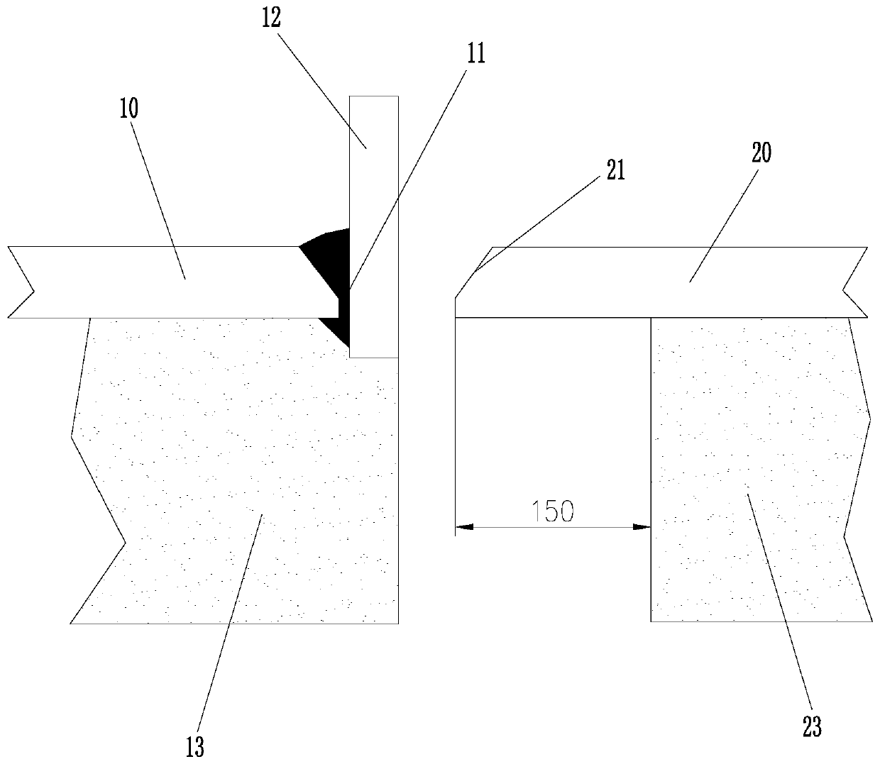
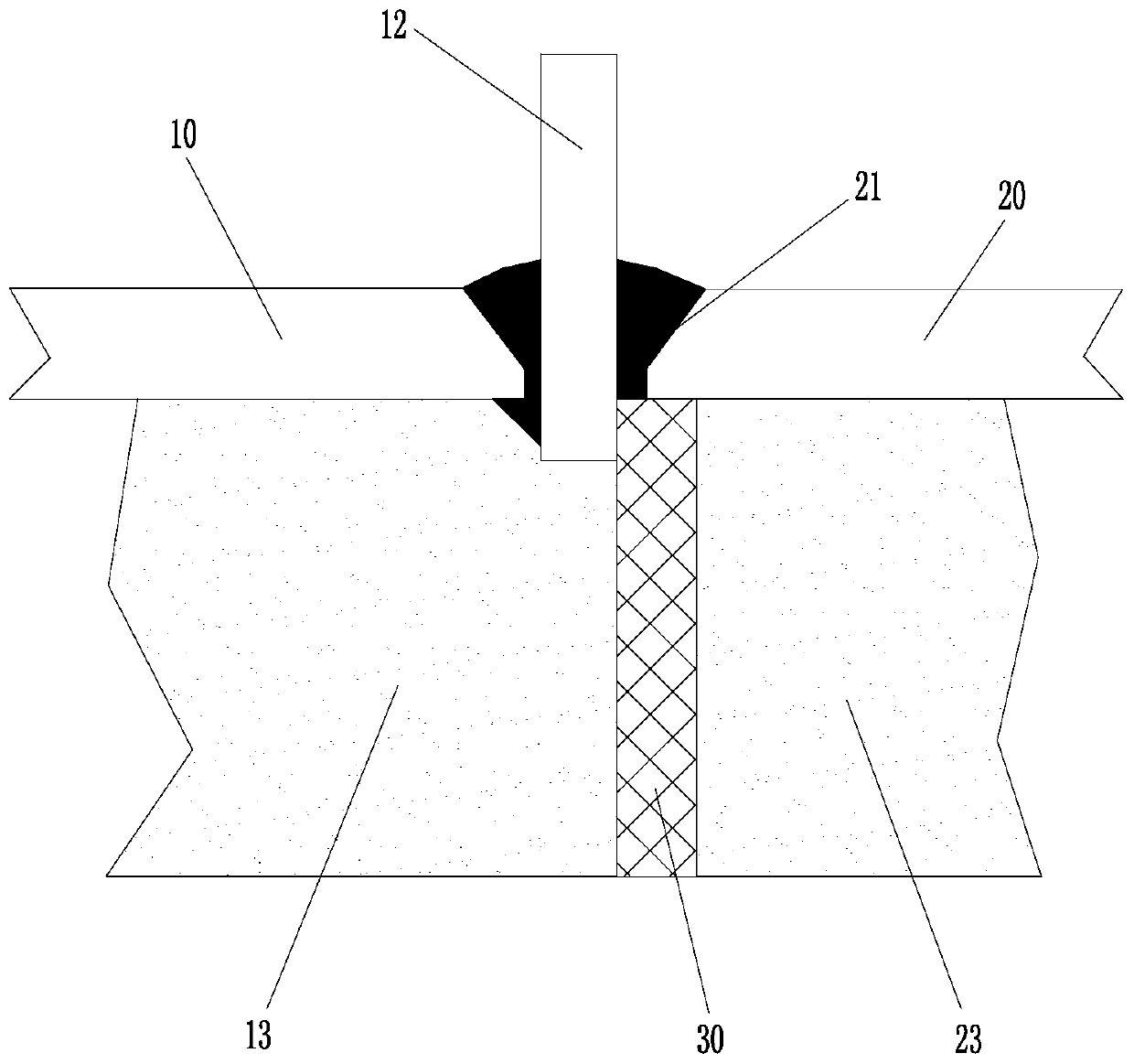
[0026] Such as figure 1 and figure 2 As shown, in this embodiment, a novel flue gas pipeline construction method of the present invention includes the following steps:

[0027] 1) Prefabricate the pre-installed flue gas pipe in sections in the prefabrication plant to form several pipe sections 10, 20;

[0028] 2) An annular plate 12 is welded on the edge of the end of one of the adjacent pipe sections 10, and the inner and outer welds of the annular plate 12 form a section 11 to ensure that the annular plate 12 has sufficient strength after welding. The annular plate 12 is 20-30mm Made of thick steel plate;

[0029] 3) Lining pouring construction is carried out to each pipe section 10, 20 to form inner lining layers 13, 23;

[0030] 4) Lift the pipe sections 10 and 20 in step 3) at...


PUM


Abstract

A novel construction method of a smoke pipeline comprises the steps of 1) prefabricating a plurality of pipe sections by sections in a prefabricating plant; 2) welding an annular plate at the side edge of the end part of one pipe section, and welding sections on interior and exterior of the annular plate; 3) pouring a lining of each pipe section to form a lining layer; 4) hoisting; measuring a clearance between every two adjacent pipe sections; and then mounting high-temperature-resistant asbestos gaskets into the clearances; 5) arranging a slope on the outer wall of the end part of another pipe section, wherein the distance from the end surface of the end part to the end surface of the lining layer is 150mm; 6) welding the slope and the annular plate in the field; and 7) examining the appearance of the welded part; and mounting the rest pipe sections after the appearance of the welded part is qualified. With the adoption of the novel construction method of the smoke pipeline, the process of entering the smoke pipeline to realize pouring or repairing construction seams after mounting of an existing smoke pipeline can be omitted; the technical problems that the aperture of the smokepipeline is subjected to ovality, and edge staggering easily occurs in a welded junction set in mounting can be solved. Therefore, the safety risk is greatly reduced; the cost is saved; and the economic benefit is increased.

Description

technical field [0001] The invention relates to the construction field of flue gas pipelines in catalytic cracking devices of petroleum refining and waste heat power generation projects in smelters, and specifically relates to a novel flue gas pipeline construction method. Background technique [0002] The existing flue gas pipeline construction methods mainly include the following two types: [0003] One is to carry out lining pouring construction after the pipeline is installed in place. This method is suitable for the construction of flue gas pipelines with a large diameter of more than 3m, and the quality is easy to check and control; [0004] The other is to carry out lining pouring construction on the prefabricated pipe section before the pipeline is installed, and then enter the interior of the pipeline to repair the construction joint after the installation is in place. [0005] The above two methods have the following defects in the actual application process: [...

Claims


Application Information

Patent Timeline
Patent Type & Authority Patents(China)
IPC IPC(8): F16L1/024F16L9/14F16L57/04B23K31/02
CPCB23K31/02F16L1/024F16L9/14F16L57/04
Inventor 袁刚曹记
Owner CHINA NAT CHEM ENG THIRD CONSTR
Learn More