
Vehicle-mounted drier

A dryer and vehicle-mounted technology, applied in dryers, drying, grain drying, etc., can solve the problems of inability to dry grains, dry wet grains, and mildew of grains, avoid breakage, and enhance durability. , the effect of increasing the firmness

Inactive Publication Date: 2018-10-16
程长春
View PDF0 Cites 0 Cited by
  • Summary
  • Abstract
  • Description
  • Claims
  • Application Information

AI Technical Summary

Problems solved by technology

[0003] Currently, the grain harvester is not equipped with a synchronous dryer. The grain harvester can only harvest grain, and cannot dry the harvested grain at the same time.
The moisture

Method used


Image

  • Vehicle-mounted drier
  • Vehicle-mounted drier
  • Vehicle-mounted drier

Examples


Embodiment 1

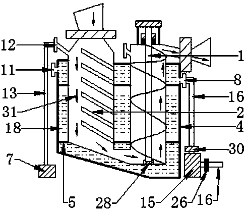
[0124] Such as figure 1 The vehicle-mounted dryer type A shown includes an auger hoist (1), a drying bin (2), a heating bin (4), a bracket (5), a vacuum unit (7), a heating device (15), Air duct (13), heat pipe (16), heat circulation pump (30).

[0125] The type A vehicle-mounted dryer is fixedly connected to the grain harvester.

[0126] The drying bin (2), the auger hoist (1) is installed in the bin of the heating bin (4).

[0127] The heating chamber (4) includes a chamber body (20) and a heat conducting medium (18).

[0128] The material of the chamber body (20) of the heating chamber (4) is a 3mm metal plate.

[0129] 1. The cross-sectional shape of the heating chamber (4) is rectangular.

[0130] 2. There is a thermal energy inlet (11) at the upper end of the heating chamber (4), and a thermal energy outlet (8) at the lower end of the heating chamber (4).

[0131] 3. A bracket (5) is installed outside the heating bin (4); the heating bin (4) is fixedly connected to ...

Embodiment 2

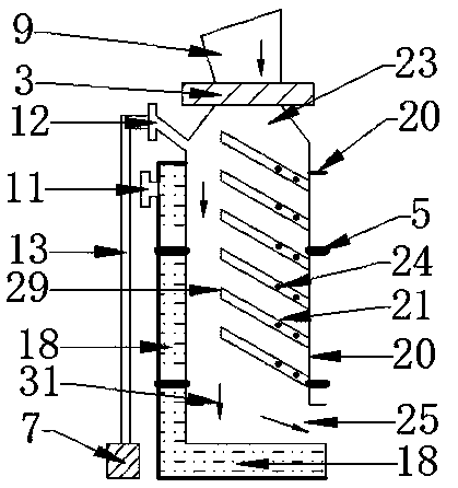
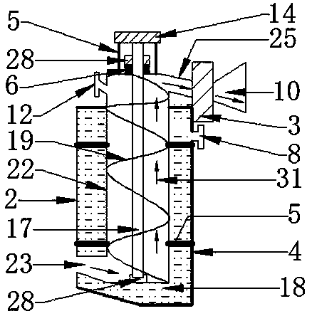
[0221] Such as Figure 4 , Figure 5 The vehicle-mounted dryer type B shown includes an auger hoist (1), a drying chamber (2), a heating chamber (4), a bracket (5), a vacuum unit (7), a heating device (15), and an air duct (13), heat pipe (16), heat circulation pump (30).

[0222] The combination structure of the vehicle-mounted dryer type B introduced in Embodiment 2 and the vehicle-mounted dryer type A introduced in Embodiment 1 will not be repeated in Embodiment 2.

[0223] The type B vehicle-mounted dryer is fixedly connected to the grain harvester.

[0224]The drying bin (2), the auger hoist (1) is installed in the bin of the heating bin (4).

[0225] The heat outlet (8) at the upper end of the heating chamber (4).

[0226] Such as Figure 4 , Figure 5 The shown drying bin (2) includes a bin body (20), a support (5), a heat exchange device (21), a discharge valve (3), and a feed hopper (9).

[0227] The heat exchange device (21) is a heat pipe heat exchanger.

[...


PUM

PropertyMeasurementUnit
Diameteraaaaaaaaaa
Thicknessaaaaaaaaaa
Heightaaaaaaaaaa

Abstract

The invention provides a vehicle-mounted drier. The vehicle-mounted drier comprises a drying bin, a heating bin, a support, an auger elevator, a vacuum unit, a heating device, a heat conduction tube,a heat conduction tube and a heat circulation pump. The drying bin and the auger elevator are installed in a bin of the heating bin. The heating device is connected with a heat energy inlet and a heatenergy outlet of the heating bin through the heat conduction tube. The drying bin comprises a bin body, a heat exchange device, a discharging valve, a feeding hopper and a heat exchange device, wherein the heat exchange device is installed in a bin of the drying bin, and an exhaust port at the upper end of the drying bin is connected to the vacuum unit through an air guide tube. The grain harvester is provided with a vehicle-mounted dryer and can be used for drying harvested cereals while the cereals are harvested, and a heat conduction medium for carrying heat energy in the vehicle-mounted dryer directly conducts heat conduction to the grains through a heat pipe, so that the heat conversion efficiency is high, the loss is small, the three-dimensional heat exchange heat conduction is adopted by the heat exchange device of the drying bin, the heat conduction heat exchange speed is improved, the vacuum drying time is shortened, and the drying time of the grains is shortened.

Description

technical field [0001] The invention relates to a dryer, in particular to a vehicle-mounted dryer installed on a grain harvester. Background technique [0002] Grain drying mechanization is the most important part of agricultural mechanization. Grain drying mechanization can assist farmers to immediately grab fresh, low-temperature and fast-drying grains that have been planted for half a year. Not only solve the problem of grain mildew and aflatoxin production, but the most important thing is to take care of the health of the people of the whole country, so that everyone can eat fresh, white, hygienic and healthy grains, and at the same time solve the problems of aging rural population, manpower, sun-drying fields Insufficient problem. [0003] At present, the grain harvester is not equipped with a synchronous dryer. The grain harvester can only harvest grain, and cannot dry the harvested grain at the same time. The moisture content of the harvested grains is high. If the...

Claims


Application Information

Patent Timeline
IPC IPC(8): F26B17/16F26B17/22F26B23/10F26B5/04A23B9/08
CPCA23B9/08F26B5/041F26B17/16F26B17/22F26B23/10F26B2200/06Y02P60/85
Inventor 程长春
Owner 程长春
Learn More