Eureka AIR delivers breakthrough ideas for toughest innovation challenges, trusted by R&D personnel around the world.

An inclination measuring device and method for a cylinder head inclined hole

A technology of measuring device and cylinder head, applied in the direction of measuring device, using optical device, instrument, etc., can solve the problems to be improved, low efficiency, etc., and achieve the effect of high detection efficiency and high measurement accuracy

Active Publication Date: 2020-08-11
舟山市宏基工业产品设计研究所
View PDF6 Cites 0 Cited by
  • Summary
  • Abstract
  • Description
  • Claims
  • Application Information

AI Technical Summary

Problems solved by technology

[0002] The cylinder head belongs to the gas distribution mechanism in the structure of the internal combustion engine. It is used to close the upper part of the cylinder, and forms a gas chamber with the cylinder and the piston. For gasoline engines, the cylinder head is also equipped with a mounting hole for fixing the spark plug. The spark plug mounting hole is set at a certain inclination angle to the cylinder head mounting plane. During quality inspection, it is necessary to detect whether the slope of the cylinder head slant hole is Up to the standard, the current detection device is generally tested by inserting the pin into the detection body. This operation method can only detect a single cylinder head, and the efficiency is low. At the same time, the physical detection method needs to be improved in terms of accuracy.

Method used


Image

  • An inclination measuring device and method for a cylinder head inclined hole
  • An inclination measuring device and method for a cylinder head inclined hole

Examples


Embodiment Construction

[0025] The embodiment of the invention provides a device and method for measuring the slope of a cylinder head slope hole.

[0026] The invention provides a device for measuring the inclination of a cylinder head inclined hole, which includes a photosensitive plate and a parallel light source. The position of the photosensitive plate is fixed along the horizontal direction, and the parallel light source is located above the photosensitive plate. Between the cylinder head and the parallel light source, the cylinder head is arranged at equal intervals on the cover transport mechanism. There are two sets of cover transport mechanisms, which are symmetrically distributed on both sides of the cylinder head. Each set of cover transport mechanism includes a conveyor belt and a driving wheel. On the side holding the cylinder head, the driving wheel drives the conveyor belt to move, and the driving wheel is connected with the intermittent movement mechanism, and the intermittent movemen...


PUM


Abstract

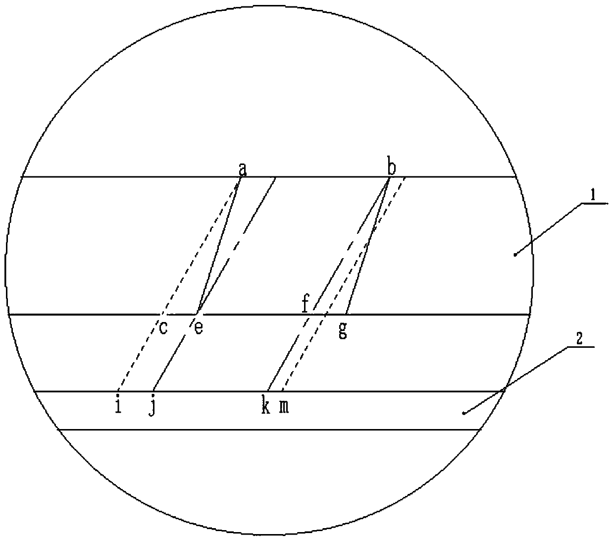
A device for measuring the inclination of inclined holes of cylinder covers comprises a light sensing plate and a parallel light source, wherein the light sensing plate is fixed in the horizontal direction, and the parallel light source is located above the light sensing plate. A cover conveying mechanism is located between the light sensing plate and the parallel light source. The cover conveyingmechanism comprises a conveying belt and a driving wheel. The cylinder covers are arranged on the conveying belt at equal intervals, and the driving wheel drives the conveying belt to move and is connected with an intermittent movement mechanism. The use method of the device is as follows: the angle of the parallel light source is adjusted to be consistent with the required inclination of the inclined holes of the cylinder covers; the cylinder covers are arranged on the conveying belt at equal intervals. The conveying belt drives the cylinder covers to move and stops when being in alignment with the parallel light source, an oval is presented on the light sensing plate, and the long axis length of the oval is measured and recorded; whether the inclination of the corresponding inclined holes of the cylinder covers meets the requirement is calculated and analyzed; and the inclination of the inclined holes of the cylinder covers is measured by means of the principle of parallel light source imaging. The precision is high, the cylinder covers are driven by the conveying belt to move, on-line detection is achieved, and the detection efficiency is high.

Description

technical field [0001] The invention relates to an inclination measuring device and method for an inclined hole in a cylinder head. Background technique [0002] The cylinder head belongs to the gas distribution mechanism in the structure of the internal combustion engine. It is used to close the upper part of the cylinder, and forms a gas chamber with the cylinder and the piston. For gasoline engines, the cylinder head is also equipped with a mounting hole for fixing the spark plug. The spark plug mounting hole is set at a certain inclination angle to the cylinder head mounting plane. During quality inspection, it is necessary to detect whether the slope of the cylinder head slant hole is Up to the standard, the current detection device is generally tested by inserting the pin into the detection body. This operation method can only detect a single cylinder head, and the efficiency is low. At the same time, the accuracy of the physical detection method needs to be improved. ...

Claims


Application Information

Patent Timeline
IPC IPC(8): G01B11/26
CPCG01B11/26
Inventor 龚雅萍
Owner 舟山市宏基工业产品设计研究所
Why Eureka
Eureka Blog
Learn More