
Adaptive selection method for adaptive region in real-time target matching and locating

A target matching and adaptive technology, applied in image analysis, image enhancement, instrument and other directions, can solve the problems of missing targets, insufficient real-time performance, and not considering the uniqueness and uniqueness of the matching area.

Inactive Publication Date: 2018-10-16
HUAZHONG UNIV OF SCI & TECH
View PDF2 Cites 2 Cited by
  • Summary
  • Abstract
  • Description
  • Claims
  • Application Information

AI Technical Summary

Problems solved by technology

The current multi-sub-area target recognition and positioning method relies on the landmarks in the field of view. Although the number of landmarks in the field of view can be guaranteed by strategies such as automatic switching, when there is a drastic change in the field of view, such as a large deviation, or too close to the target When , the number of switching landmarks in the field of view is insufficient, resulting in a decrease in the accuracy and accuracy of fusion recognition, and even loss of targets
[0005] At present, in the existing technology, the method of multi-feature fusion is used for automatic adaptation area selection. The selection criterion uses three features of edge density, average edge strength, and edge direction dispersion to form a comprehensive adaptation feature index, but there is no uniqueness for the adaptation area. analysis of uniqueness and uniqueness
In the prior art, USAN geometric features are also used for template selection, which has a large amount of calculation, insufficient real-time performance, and does not consider the uniqueness and uniqueness of the matching area.

Method used


Image

  • Adaptive selection method for adaptive region in real-time target matching and locating
  • Adaptive selection method for adaptive region in real-time target matching and locating
  • Adaptive selection method for adaptive region in real-time target matching and locating

Examples


Embodiment Construction

[0083] In order to make the object, technical solution and advantages of the present invention clearer, the present invention will be further described in detail below in conjunction with the accompanying drawings and embodiments. It should be understood that the specific embodiments described here are only used to explain the present invention, not to limit the present invention. In addition, the technical features involved in the various embodiments of the present invention described below can be combined with each other as long as they do not constitute a conflict with each other.

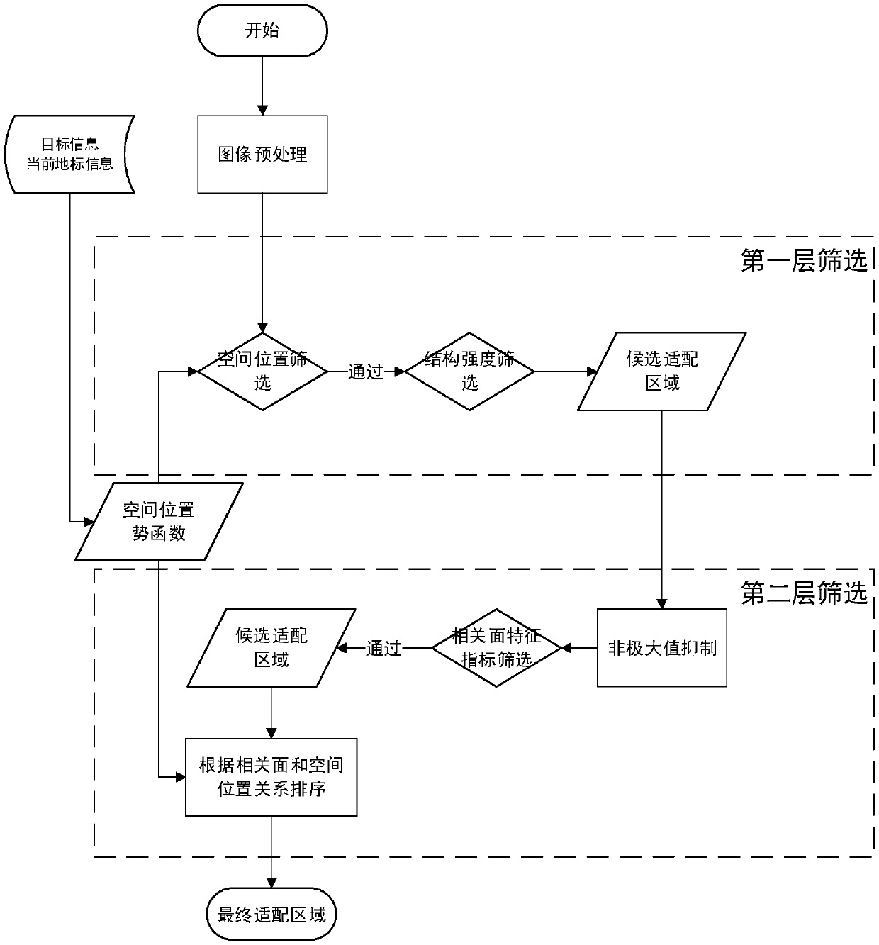
[0084] like figure 1 Shown, the inventive method comprises the following steps:

[0085] (1) Carry out noise reduction and threshold segmentation processing on the image to be processed, divide the foreground and background in the image to be processed, and then divide the image to be processed into multiple sub-blocks;

[0086] (11) In order to suppress imaging noise and fine texture interfer...


PUM


Abstract

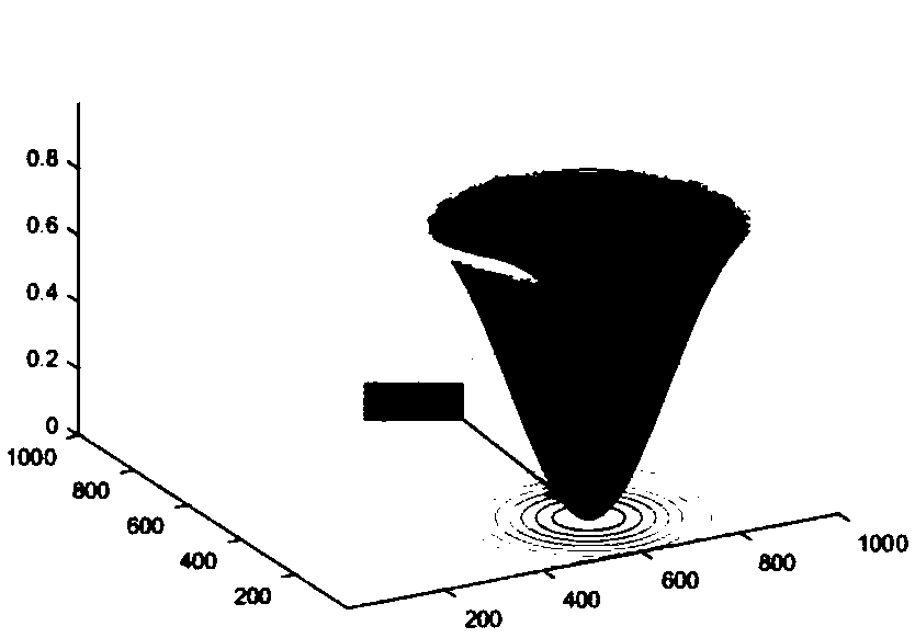
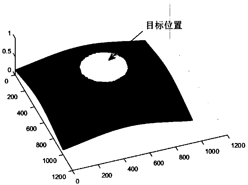
The invention discloses an adaptive selection method for an adaptive region in real-time target matching and locating, and belongs to the technical field of computer image identification. The method comprises the steps of performing preprocessing and threshold segmentation on a real-time image; building a potential function by utilizing a spatial position relationship between a landmark and a target; by utilizing a local region stability index and a local region intensity index, performing first layer screening under the constraint of a spatial position potential function; performing non-maximum suppression on obtained candidate matching regions, and removing the regions with the relatively high overlapping degree; then performing correlation surface feature index screening and sorting; and finally selecting an optimal adaptive region through a potential function iterative strategy. Under the condition of insufficient matchable region quantity in target matching identifying and locating processes, the adaptive region which is abundant in information amount, is stable and reliable and is free of a repeat mode is selected in real time adaptively.

Description

technical field [0001] The invention belongs to the technical field of computer image recognition, and more specifically relates to a method for adaptively selecting an adaptation area in real-time target matching and positioning. Background technique [0002] Target matching and positioning technology is a key technology in the field of computer vision, which has important research and application value in aircraft navigation, video surveillance, image search and other fields. The target matching and positioning technology based on image matching refers to using the obtained real-time image data and platform attitude information on the imaging platform to match with the pre-stored reference image data to complete the matching and positioning of the target. With the rapid development of information technology, target detection and recognition technology is playing an increasingly important role in aircraft navigation and other fields. [0003] In practical applications, due...

Claims


Application Information

Patent Timeline
IPC IPC(8): G06T7/223G06T7/73G06T5/00G06T7/11G06T7/187G06T7/194
CPCG06T7/11G06T7/187G06T7/194G06T7/223G06T7/73G06T2207/20021G06T2207/20221G06T2207/30184G06T5/70
Inventor 王岳环黄辛未谷海国方馨
Owner HUAZHONG UNIV OF SCI & TECH
Learn More