
Crop fertilizing device

A fertilization device and crop technology, applied in fertilization devices, agriculture, planting methods, etc., can solve the problems of waste, burned roots, low fertilizer utilization rate, etc., and achieve the effect of improving absorption rate and avoiding lumps

Inactive Publication Date: 2018-10-19
重庆市保役农业开发有限责任公司
View PDF5 Cites 6 Cited by
  • Summary
  • Abstract
  • Description
  • Claims
  • Application Information

AI Technical Summary

Problems solved by technology

However, rational fertilization can give full play to the effect of fertilizer on increasing production, and is an important measure to achieve high yield, stable yield and low cost, while unreasonable fertilization will lead to reduced yield, and even result in burnt seedlings, plant wilting and other consequences
[0003] At present, generally small-scale farmers use manual fertilization, which has low work efficiency, high manual labor intensity, and insufficient fertilization depth, which causes fertilizer to be volatile, lost or difficult to reach the roots of crops, which is not conducive to crop absorption and causes fertilizer utilization. Low
Large-scale farmers will use fertilizer applicators to fertilize. Basically, the fertilizer applicators are equipped with plowshares in the front to open furrows, and there are fertilizer guide pipes in the rear to guide the fertilizer into the furrows opened by the plowshares. This method of fertilization will lead to some fertilizers. If it is close to the crops, the roots will be burned, and some fertilizers are far away from the crops, so that the roots cannot absorb nutrients. At the same time, the utilization rate of fertilizers is not high, resulting in waste

Method used


Image

  • Crop fertilizing device
  • Crop fertilizing device
  • Crop fertilizing device

Examples


Embodiment Construction

[0023] Further detailed explanation through specific implementation mode below:

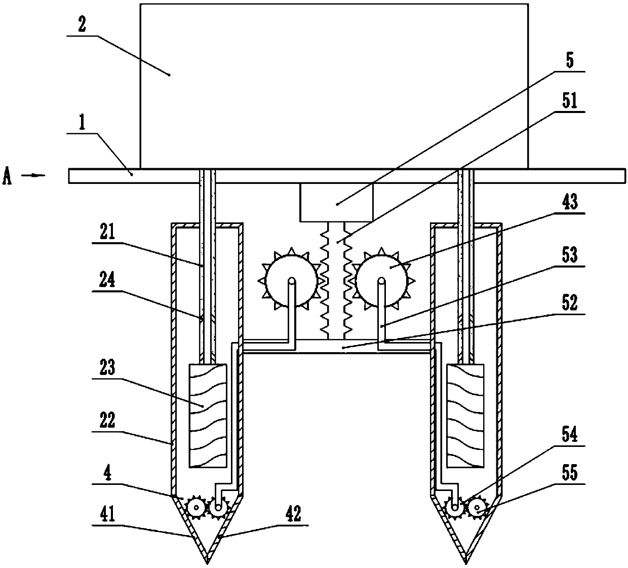
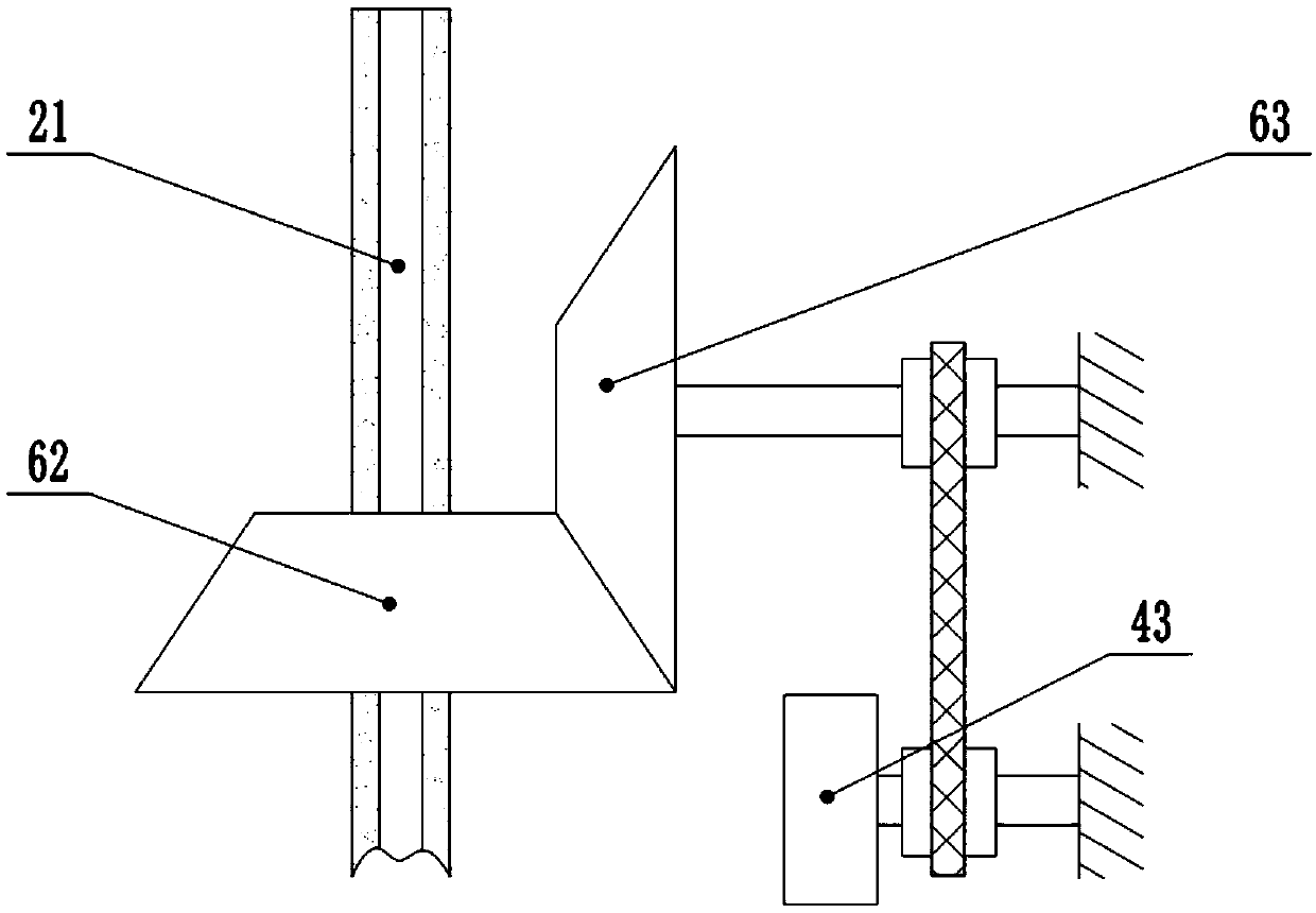
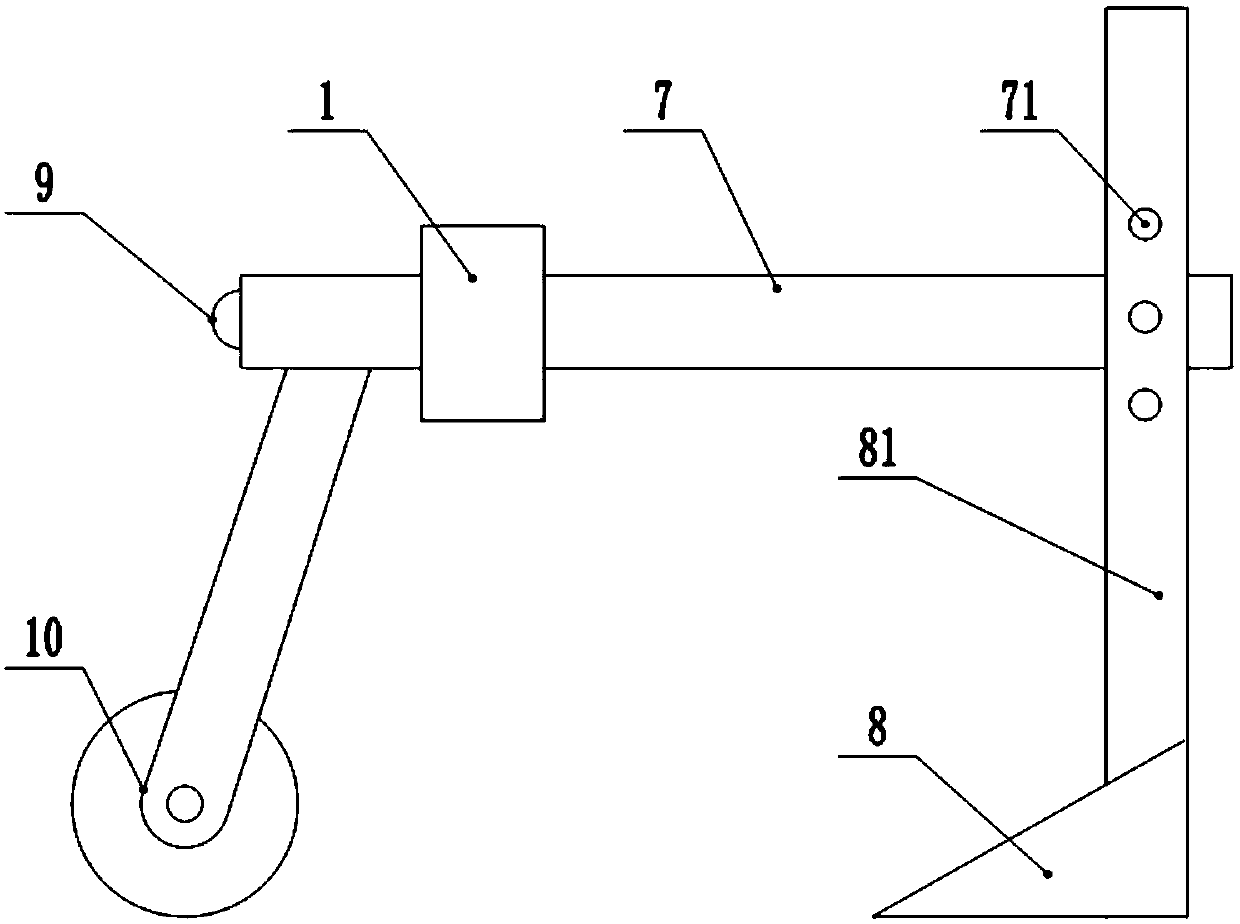
[0024] The reference numerals in the drawings of the description include: baffle plate 1, fertilizer box 2, fertilization pipe 21, stirring box 22, stirring rod 23, discharge hole 24, hole opener 4, first hole opening plate 41, second opening hole Hole plate 42, first gear 43, cylinder 5, rack 51, linkage plate 52, flexible shaft 53, third gear 54, fourth gear 55, first bevel gear 62, second bevel gear 63, beam 7, adjustment Hole 71, plow share 8, support arm 81, draw ring 9, support wheel 10.

[0025] The embodiment is basically as attached figure 1 Shown:

[0026] A crop fertilization device, including a frame, a baffle 1, a fertilizer box 2 and a fertilization mechanism, the fertilizer box 2 is located above the baffle 1, the fertilization mechanism is located below the baffle 1, a cylinder 5 is arranged at the bottom of the baffle 1, and the bottom of the cylinder 5 is A rack 51 is fixed, ...


PUM


Abstract

The invention discloses a crop fertilizing device. The crop fertilizing device comprises a rack, a baffle, a fertilizer box and fertilizing mechanisms. An air cylinder is arranged at the bottom of thebaffle, a rack is fixed to the air cylinder, a linkage plate is fixed to one end of the rack, flexible shafts are rotatably connected to the rack, first gears meshed with the rack are connected to the outer circumferences of the flexible shafts through one-way bearings, and the fertilizing mechanisms are connected to the linkage plate; each fertilizing mechanism includes a fertilizing pipe, a stirring box and a hole opener, a third gear and a fourth gear which are meshed with each other are arranged in each hole opener, multiple discharge holes are formed in each fertilizing pipe, and a stirring rod is connected to the bottom of each fertilizing pipe; the linkage plate is hollow and is fixedly connected to the outer walls of the stirring boxes, and the flexible shafts extend into the linkage plate and penetrate through the walls of the stirring boxes to be connected with the corresponding third gears; the fertilizing pipes are provided with first bevel gears meshed with second bevel gears, and conveying mechanisms are arranged between rotating shafts of the second bevel gears and the flexible shafts on the first gears. The device can solve the problem of a seedling burning phenomenon of crops, and the absorption rate of the crops on fertilizer is increased.

Description

technical field [0001] The invention belongs to the technical field of agricultural machinery and specifically discloses a crop fertilization device. Background technique [0002] When the soil cannot provide the nutrients needed for the growth and development of crops, it is necessary to fertilize the crops to supplement their nutrients. However, rational fertilization can give full play to the effect of fertilizer on increasing production, which is an important measure to achieve high yield, stable yield and low cost, while unreasonable fertilization will lead to reduced yield, and even result in burnt seedlings and plant wilting. [0003] At present, generally small-scale farmers use manual fertilization, which has low work efficiency, high manual labor intensity, and insufficient fertilization depth, which causes fertilizer to be volatile, lost or difficult to reach the roots of crops, which is not conducive to crop absorption and causes fertilizer utilization. Low. La...

Claims


Application Information

Patent Timeline
IPC IPC(8): A01B49/06A01C15/00A01C5/04
CPCA01B49/06A01C5/04A01C15/00
Inventor 雷起碧
Owner 重庆市保役农业开发有限责任公司
Learn More