Touch sensation perception diagnosis device

A diagnostic device and tactile sensing technology, applied in diagnosis, diagnostic recording/measurement, diagnosis using pressure, etc., can solve problems such as inconvenient, inconvenient and inaccurate diagnosis of carrying equipment

Inactive Publication Date: 2018-10-19
陈明珠
View PDF5 Cites 0 Cited by
  • Summary
  • Abstract
  • Description
  • Claims
  • Application Information

AI Technical Summary

Problems solved by technology

[0002] At present, when treating and diagnosing in major hospitals, especially when examining the body in the neurology department, it is often necessary to use neurology diagnostic devices, such as percussion hammers, stylus, and flashlights. It is inconvenient to carry these devices, and the neural network is spread all over. A little problem with every nerve in the whole body will cause some diseases, so these devices are needed for some preliminary diagnosis. Although these devices are simple, they are very useful in the process of treatment and diagnosis, but they are very inconvenient
[0003] Existing technologies generally can only be diagnosed through preliminary manual diagnosis. Experienced medical personnel need to conduct tests and diagnoses to judge the physical function and nerve perception feedback of neurology patients, or through a single tactile response test method. Test and inspection, this kind of method cannot determine the test results through scientific and accurate data testing, which may easily cause inaccurate diagnosis and affect the recovery of patients. If things go on like this, it will greatly increase the work difficulty of medical staff

Method used


Image

  • Touch sensation perception diagnosis device
  • Touch sensation perception diagnosis device
  • Touch sensation perception diagnosis device

Examples


Embodiment Construction

[0022]Through the description of the embodiments below, the specific implementation of the present invention includes the shape, structure, mutual position and connection relationship between the various parts, the function and working principle of each part, the manufacturing process and the operation and use method of the various components involved. etc., to make further detailed descriptions to help those skilled in the art have a more complete, accurate and in-depth understanding of the inventive concepts and technical solutions of the present invention.

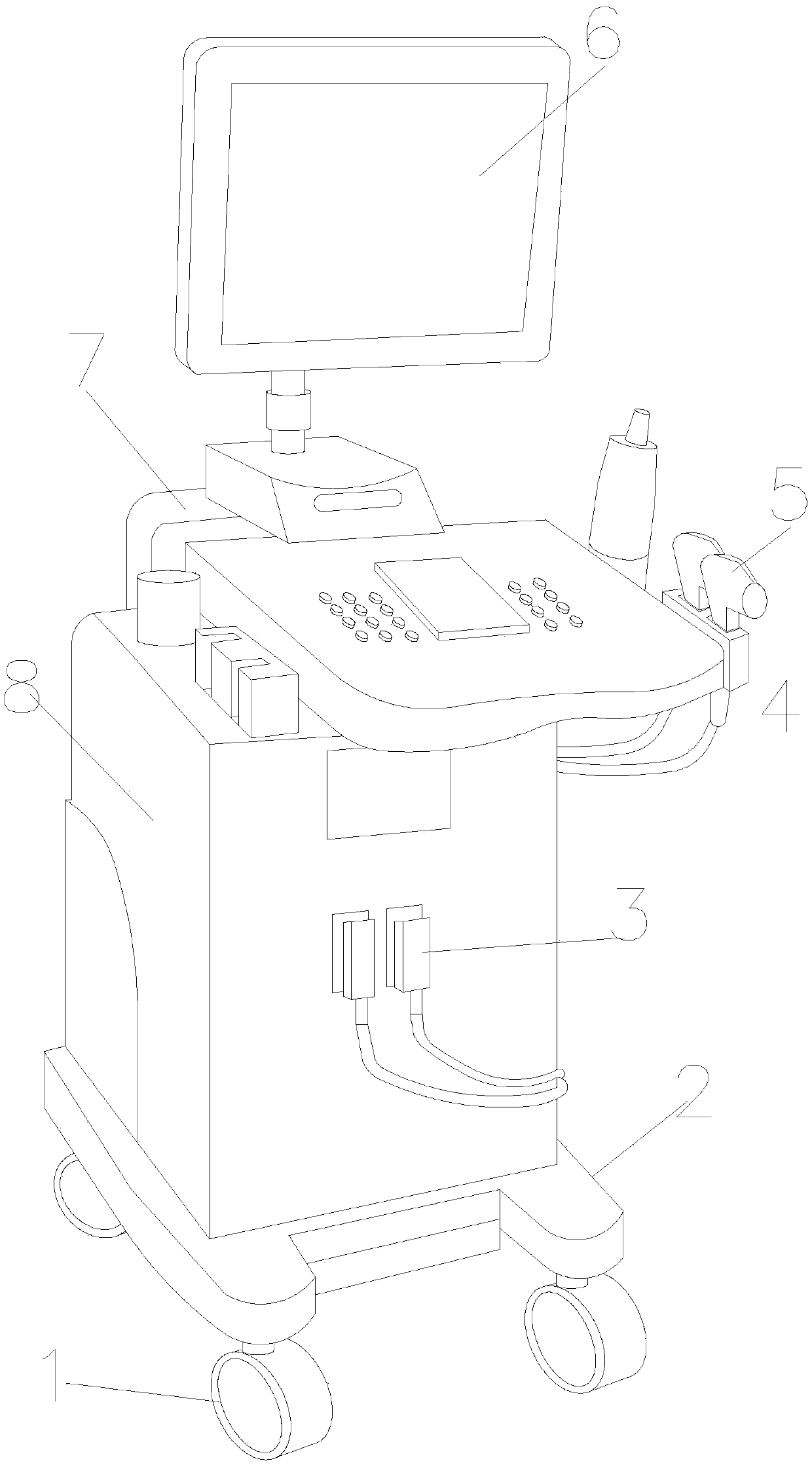
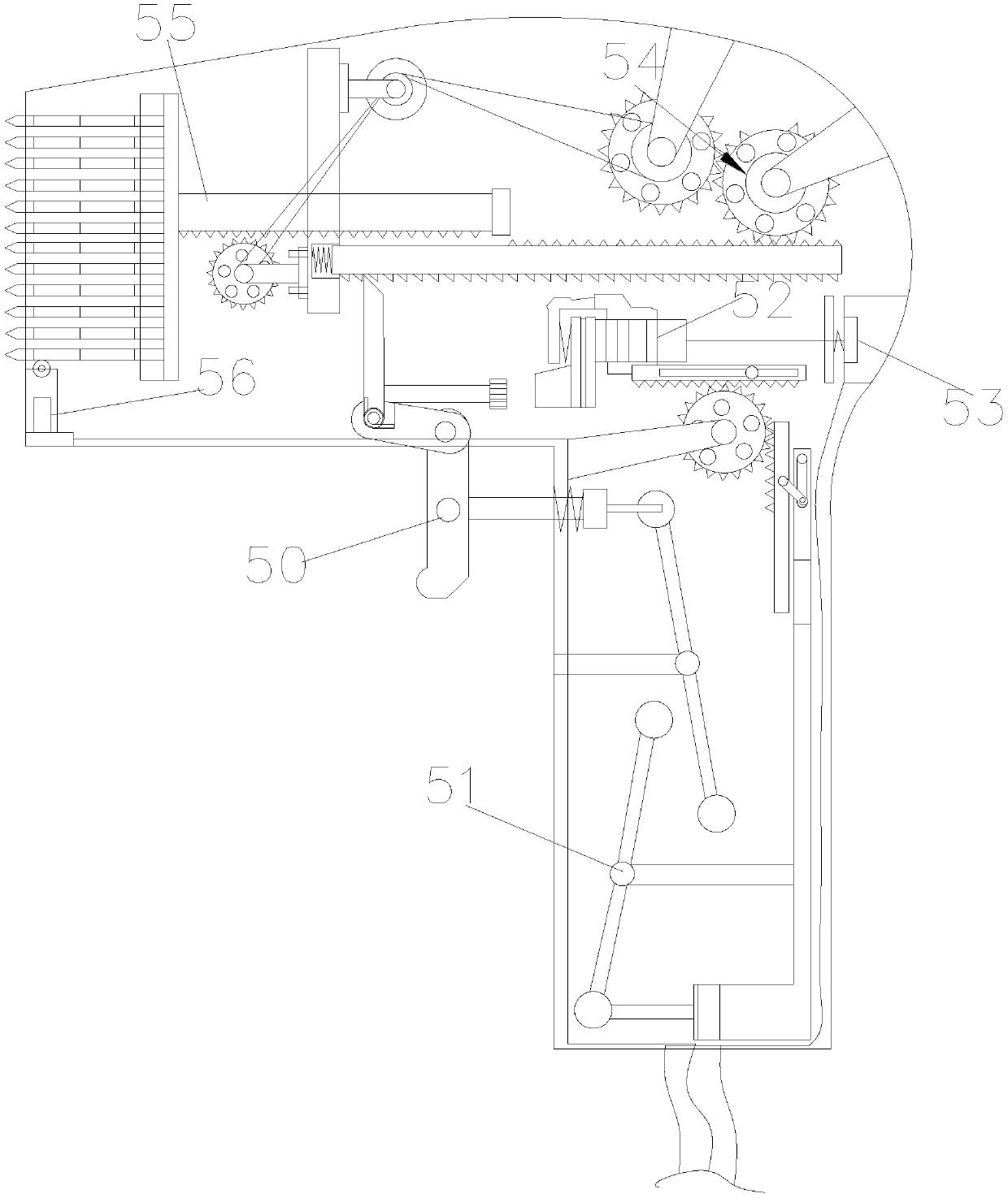
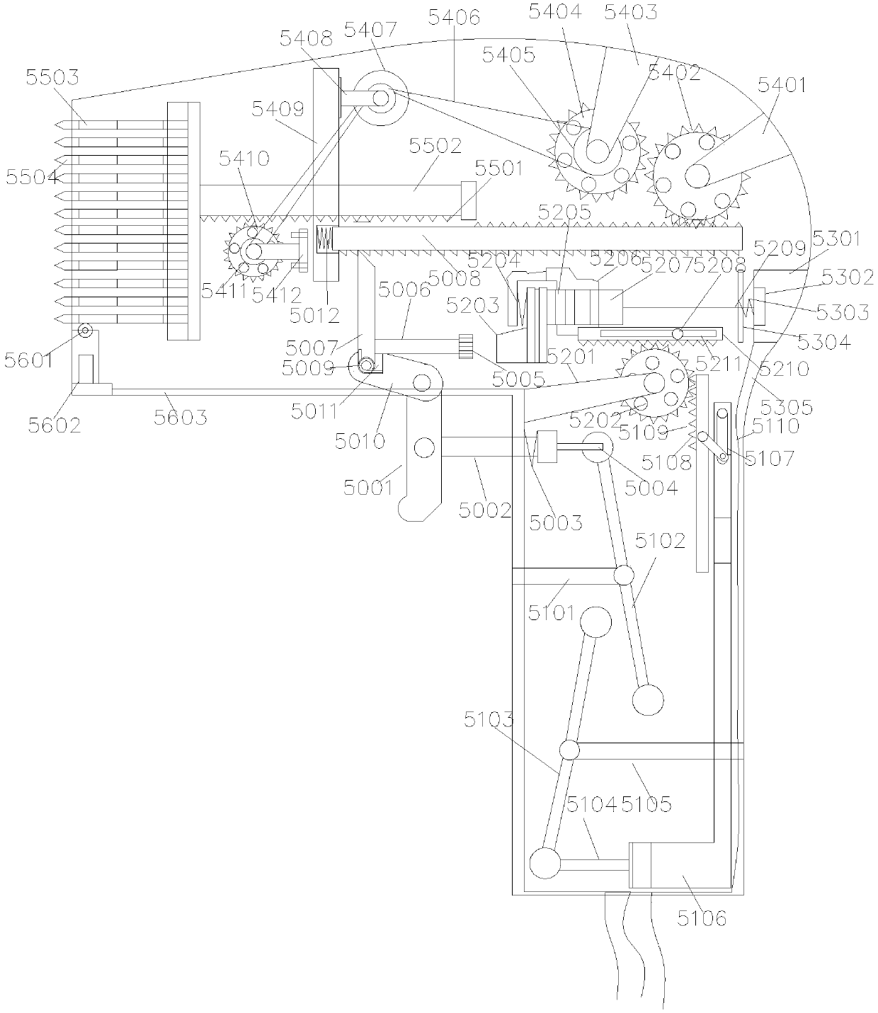
[0023] see Figure 1-Figure 4 , the present invention provides a neurology tactile perception diagnostic device: its structure includes a moving roller 1, a base 2, a sensor connector 3, a control panel 4, a tactile sensing diagnostic device 5, a display screen 6, a mobile frame 7, and a body 8; The moving roller 1 is installed on the bottom of the base 2 and is rollingly connected with the ground, the base 2 and the bo...


PUM


Abstract

The invention discloses a touch sensation perception diagnosis device. The touch sensation perception diagnosis device structurally comprises moving idler wheels, a base, a sensing connector, a control panel, a touch sensation perception diagnosis device body, a display screen, a movable shelf and a device body; the moving idler wheels are installed at the bottom of the base and rollably connectedwith the ground, the base and the device body are fixedly connected to the bottom, and the sensing connector makes the touch sensation perception diagnosis device body connected to the device body; the control panel makes the moving shelf connected to the top of the device body, the touch sensation perception diagnosis device body is installed at the right side of the control panel and electrically connected with the device body, and the display screen and the movable shelf are perpendicular to each other and are arranged on the upper portion. Through the mutual combination of all the parts,by manually controlling a neurological examination tool to detect a patient to different degrees, and data is transmitted to medical equipment; through combined analysis of scientific and accurate data testing and personnel experiences, the accuracy of diagnosing the illness condition of the patient can be improved, and the working difficulty can be reduced; through the arrangement of stirring sheets and backsprings, reset of probes is facilitated, and the touch sensation perception diagnosis device is convenient to use next time.

Description

technical field [0001] The invention relates to the technical field of tactile sensing devices, in particular to a tactile sensing diagnostic device. Background technique [0002] At present, when treating and diagnosing in major hospitals, especially when examining the body in the neurology department, it is often necessary to use neurology diagnostic devices, such as percussion hammers, stylus, and flashlights. It is inconvenient to carry these devices, and the neural network is spread all over. A little problem with every nerve in the whole body will cause some diseases, so these devices are needed for some preliminary diagnosis. Although these devices are simple, they are very useful in the process of treatment and diagnosis, but they are very inconvenient. [0003] Existing technologies generally can only be diagnosed through preliminary manual diagnosis. Experienced medical personnel need to conduct tests and diagnoses to judge the physical function and nerve perceptio...

Claims


Application Information

Patent Timeline
IPC IPC(8): A61B5/00
CPCA61B5/0053A61B5/4005
Inventor 陈明珠
Owner 陈明珠
Why Eureka
Try Eureka