
Intelligent punching die

A stamping die and intelligent technology, which is applied in the field of intelligent stamping dies, can solve the problems of being unable to ensure that the flanges on both sides of the stamping opening are parallel to each other, low automation level, and low processing accuracy.

Inactive Publication Date: 2018-10-19
安祖桂
View PDF4 Cites 5 Cited by
  • Summary
  • Abstract
  • Description
  • Claims
  • Application Information

AI Technical Summary

Problems solved by technology

The output end of the press is connected with the lower mold base for placing the blank and the upper mold base for the stamping action; however, after stamping the general blank, the workpiece undergoes plastic deformation, because once the blank loses external force after deformation, the blank There will be a certain amount of springback. For example, when metal parts are processed by intelligent stamping dies for U-shaped parts, once the upper mold base and the lower mold base are parted, the opening of the U-shaped part will expand outwards to form a bell-shaped structure. , it is impossible to ensure that the flanging on both sides of the stamping opening is a parallel workpiece; that is to say, the intelligent stamping die in the prior art has the deficiency of low machining accuracy; low level of automation

Method used


Image

  • Intelligent punching die
  • Intelligent punching die
  • Intelligent punching die

Examples

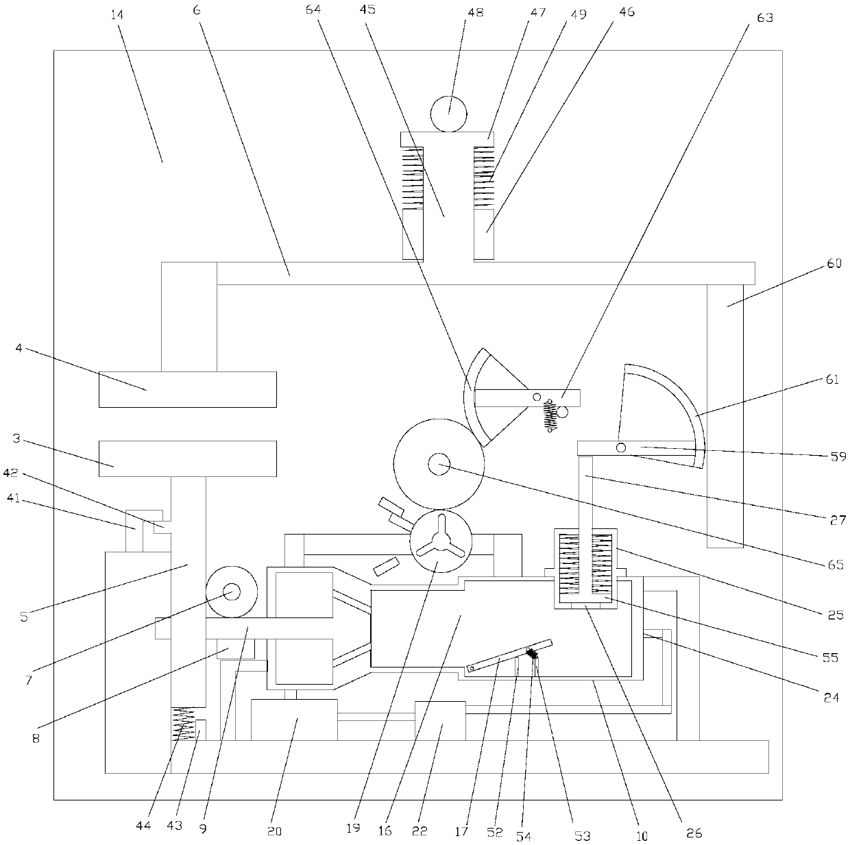
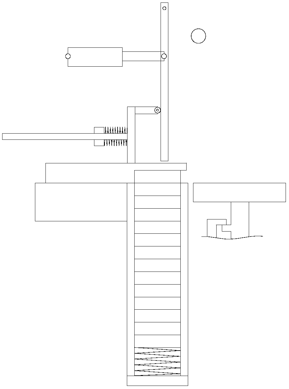
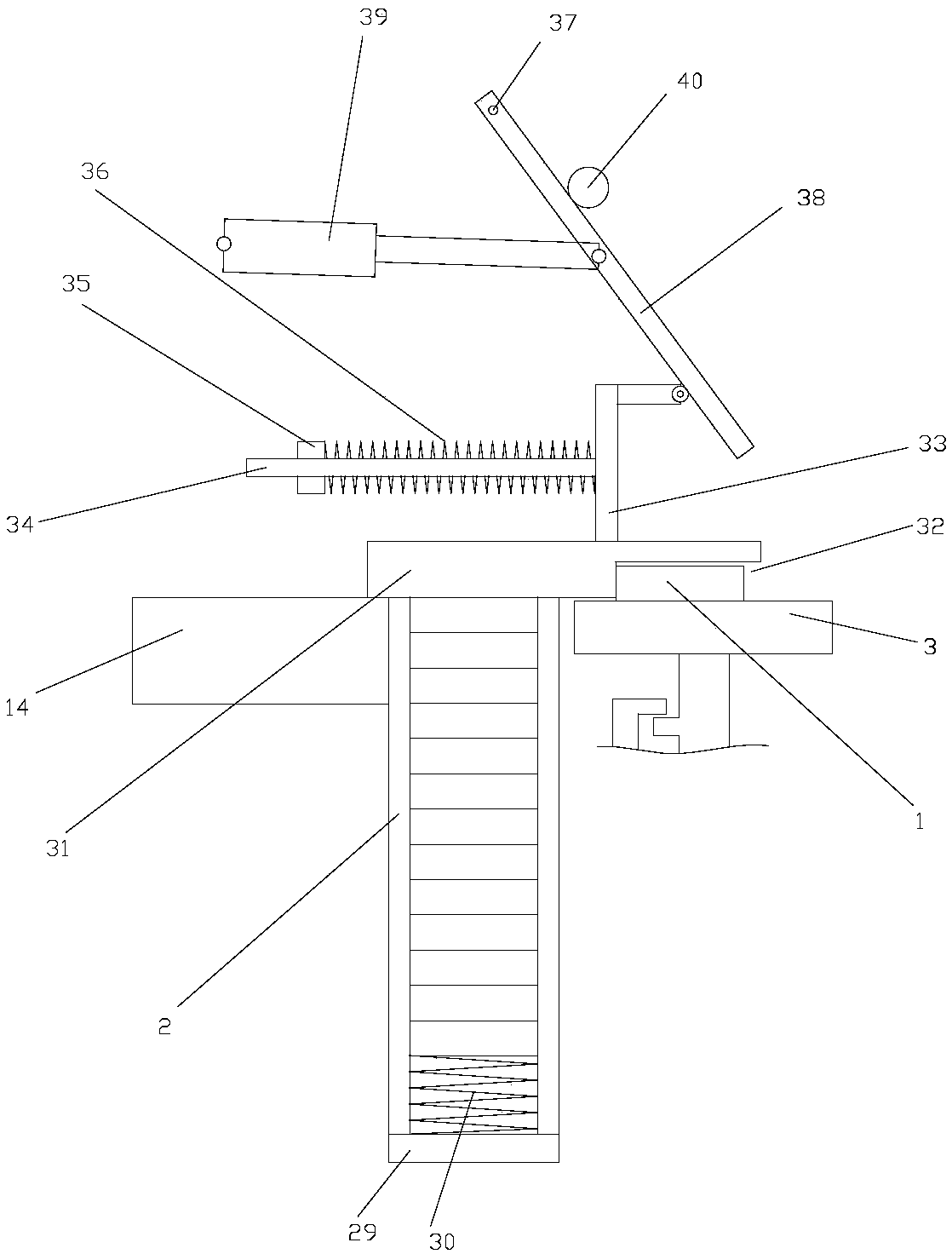

Embodiment Construction

[0026] The present invention will be further described below in conjunction with the accompanying drawings and specific embodiments.

[0027] As shown in the figure, the intelligent stamping die of the present invention includes a base 14 on which the upper mold base 4 and the lower mold base 3 are slidably connected. The base 14 is provided with a barrel 2 for storing the blank 1. The base 14 There is a push assembly for pushing the blanks 1 in the barrel 2 to the lower mold base 3 one by one; All slide along the vertical direction, and then ensure that the upper mold base 4 and the lower mold base 3 can be clamped. On the base 14; the support rod 5 is provided with a first linear rack, the base 14 is rotatably connected with the first gear 7 for meshing with the first linear rack, and the base 14 is slidably connected by the guide block 8 There is a stopper rod 9, which is provided with a second linear rack for meshing transmission with the first gear 7; a valve seat 10 is ...


PUM


Abstract

The invention discloses an intelligent punching die. The intelligent punching die comprises a base 14, the base 14 is in sliding connection with an upper die base 4 and a lower die base 3, the base 14is provided with a material barrel 2 for storing blank pieces 1, and the base 14 is provided with a pushing assembly for pushing the blank pieces 1 in the material barrel 2 to the lower die base 3 one by one. The lower die base 3 and the upper die base 4 are provided with a supporting rod 5 and a sliding frame 6 correspondingly, wherein the supporting rod 5 and the sliding frame 6 slide in the vertical direction, accordingly, it is ensured that the upper die base 4 and the lower die base 3 can be subjected to die assembly, and the supporting rod 5 and the sliding frame 6 are in sliding connection to the base 14 through a first sliding assembly and a second sliding assembly in the vertical direction. The intelligent punching die higher in automation level and higher in machining precisionis provided.

Description

technical field [0001] The invention relates to the field of mechanical engineering, in particular to an intelligent stamping die. Background technique [0002] Intelligent stamping die is a kind of process equipment that processes metal or non-metallic materials into parts in cold stamping processing; specifically, at room temperature, the mold installed on the press is used to apply pressure to the material to make it separate. Or plastic deformation, and then a pressure processing method to obtain the desired structure. The setting of the power source is to purchase presses of different specifications or models according to the needs of different working conditions. The output end of the press is connected with the lower mold base for placing the blank and the upper mold base for the stamping action; however, after stamping the general blank, the workpiece undergoes plastic deformation, because once the blank loses external force after deformation, the blank There will ...

Claims


Application Information

Patent Timeline
IPC IPC(8): B21D43/04B21D37/10B21D22/02B21D45/04
CPCB21D43/04B21D22/02B21D37/10B21D45/04
Inventor 安祖桂
Owner 安祖桂
Learn More