Forming method of complex structural part

A technology for complex structures and structural parts, applied in the improvement of process efficiency, control equipment for metal extrusion, metal extrusion, etc., can solve problems such as difficult to adapt to structural iterative design and rapid response, and achieve high-performance manufacturing, fast and efficient manufacturing , the effect of improving the connection performance

Active Publication Date: 2018-10-19
BEIJING HANGXING MACHINERY MFG CO LTD
View PDF6 Cites 6 Cited by
  • Summary
  • Abstract
  • Description
  • Claims
  • Application Information

AI Technical Summary

Problems solved by technology

[0002] The requirements for the development cycle of the new generation of weapons and equipment are gradually increasing, and most of the structural parts are double-sided asymmetri

Method used


Image

  • Forming method of complex structural part
  • Forming method of complex structural part
  • Forming method of complex structural part

Examples


Embodiment 1

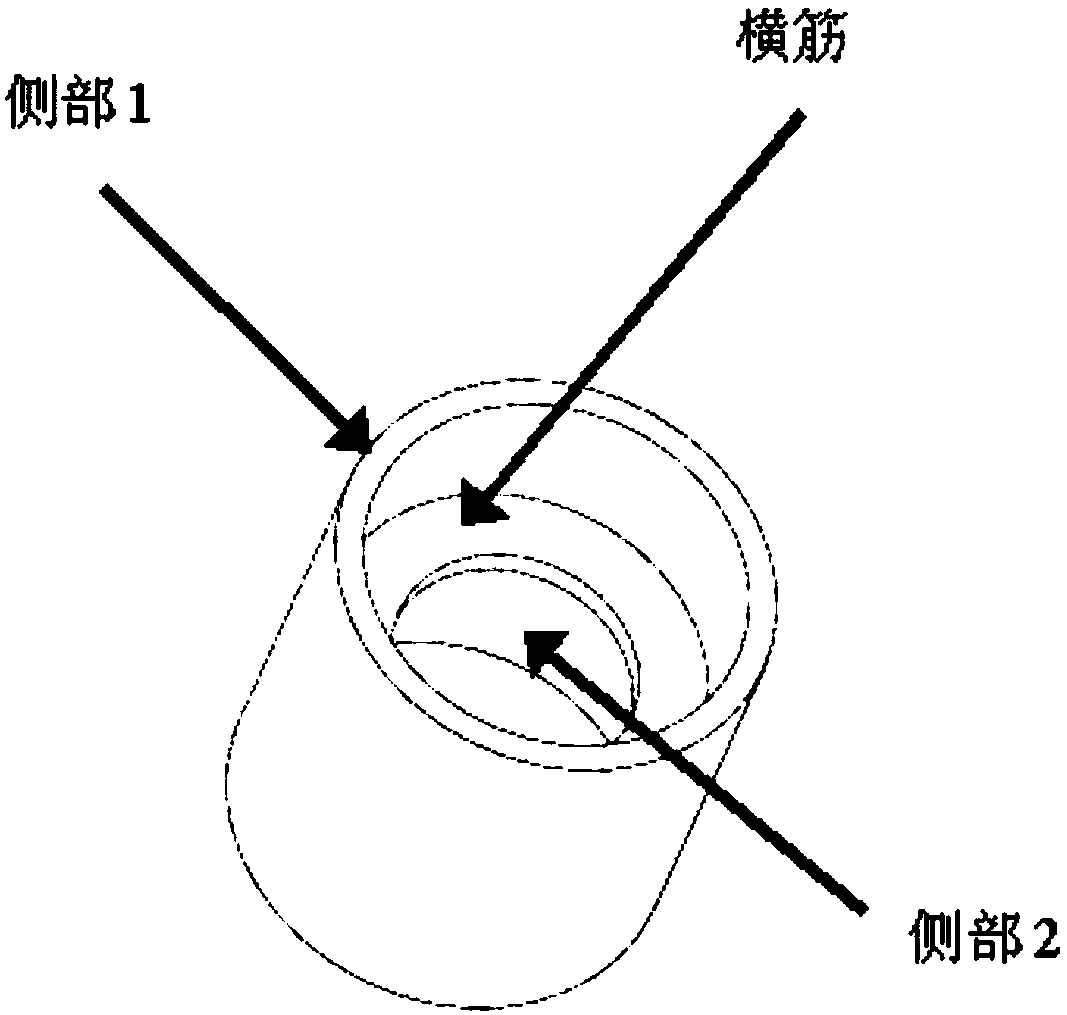
[0043] The structural part to be formed is: thin-walled double-sided asymmetric deep cavity structure, the material is 5A06 aluminum alloy, and the structural diagram is as follows figure 1 As shown, the basic wall thickness is 10mm, and the structure to be formed includes side 1, side 2 and transverse rib; the steps of the forming method of the structure to be formed include:

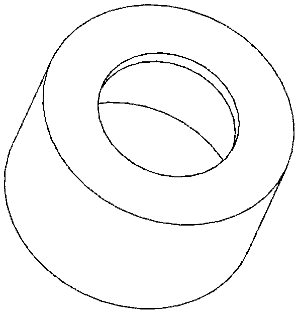
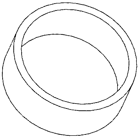
[0044] (1) The structural part to be formed is divided into two parts, the side part 2 and the transverse rib are used as the first matrix, such as figure 1 As shown, the side part 1 is used as the second base body, such as figure 2 shown;

[0045] (2) adopting the first base body in manufacturing step (1) by hot extrusion forming method;

[0046] (3) Manufacturing the second substrate on the first substrate manufactured in step (2) by using arc additive manufacturing technology;

[0047] In the described step (3), the detailed steps of manufacturing the second substrate are:

[0048] Firstly, the...

Embodiment 2

[0054] The structural part to be formed is: a constant cross-section structure with a circular boss, and the material is 5A06 aluminum alloy. The schematic diagram of the structure is as follows Figure 4 As shown, the basic wall thickness is 10mm, and the steps of the forming method of the structure to be formed include:

[0055] (1) Divide the structural part to be formed into two parts, and use a square frame with equal cross-section as the first matrix, such as Figure 5 As shown, the circular boss is used as the second base, such as Image 6 shown;

[0056] (2) adopting the first base body in manufacturing step (1) by hot extrusion forming method;

[0057] (3) Manufacturing the second substrate on the first substrate manufactured in step (2) by using arc additive manufacturing technology;

[0058] In the described step (3), the detailed steps of manufacturing the second substrate are:

[0059] Firstly, the area to be added on the first substrate is polished flat; seco...


PUM

PropertyMeasurementUnit
Tensile strengthaaaaaaaaaa

Abstract

The invention relates to a forming method of a complex structural part, and belongs to the technical field of precision forming machining. The complex structural part is of an equal-cross-section structure with a transverse rib or a boss (except for the transverse rib or the boss, the other portion is of the equal-cross-section structure), or is of a double-side asymmetric deep cavity structure with a web plate. The composite manufacturing method of combining the arc additive and hot extrusion makes full use of the characteristics of high efficiency and low cost of the hot extrusion and arc additive manufacturing technology, so that the defect that the arc additive method and the hot extrusion method can only form a relatively simple structural part is avoided, and rapid and efficient manufacturing of the complex structural part is realized; and secondly, the mechanism based on the fact that the melting depth can be increased by an active agent is utilized to coat a region needs to undergo arc additive manufacturing on an extrusion substrate with a layer of active agent, so that the connecting performance of an interface is further improved, and the high-performance manufacturing of the complex structural part is realized.

Description

technical field [0001] The invention relates to a forming method of a complex structural part, which belongs to the technical field of precision forming. The complex structural part is an equal-section structure with transverse ribs or bosses (except the transverse ribs or bosses, others are equal-sectional structures) Or a bilateral asymmetric deep cavity structure with webs. Background technique [0002] The requirements for the development cycle of the new generation of weapons and equipment are gradually increasing, and most of the structural parts are double-sided asymmetric deep cavity structures or variable cross-section structures. Traditional casting and other technologies are difficult to adapt to the rapid response to structural iterative design. Contents of the invention [0003] The technical problem solved by the present invention is to overcome the deficiencies in the prior art and propose a method for forming complex structural parts, which is used to form ...

Claims


Application Information

Patent Timeline
IPC IPC(8): B22F7/08B22F3/105B21C31/00B33Y10/00
CPCB21C31/00B22F3/105B22F7/08B22F2003/1051B22F2003/1052B33Y10/00Y02P10/25
Inventor 何智王志敏郭晓琳张云鹏吴复尧张铁军
Owner BEIJING HANGXING MACHINERY MFG CO LTD
Why Eureka
Try Eureka