Clamping device and clamping method for machinery manufacturing

A clamping device and mechanical manufacturing technology, which is applied in the direction of grinding workpiece supports, etc., can solve the problems of manual edge changing and grinding, and achieve the effects of saving time, not easy to drop, and convenient to use

Pending Publication Date: 2018-10-19
盐城市诚益通机械制造有限责任公司
0 Cites 0 Cited by

AI-Extracted Technical Summary

Problems solved by technology

[0003] The purpose of the present invention is to provide a clamping device and a clamping method for mechanical manufacturing, to solve the existing problem in the above-menti...

Method used

Fixed block 14 is installed on the side of connecting block 13, and spring 15 is installed on the fixed block 14, and the top of spring 15 is provided with spring pad 16, and the spring pad 16 of fixed block 14 and spring 15 upper ends is provided with 2 groups , and the spring pads 16 on the fixed block 14 and the spring 15 are respectively arranged on the connecting block 13 and the movable shaft 21, so that it is convenient to put in parts of different sizes and shapes that need to be clamped. The spring 15 is provided with 3 groups, and the spring 15 The bottom end is welded on the top of the fixed block 14, and the upper end of the spring 15 is integrated with the spring pad 16, so that the spring 15 is firmly installed on the top, and it is not easy to drop when clamping the parts. The shape of the spring pad 16 and the fixed block 14 are uniform It is arc-shaped, and the diameter of the spring pad 16 is the same as that of...

Abstract

The invention discloses a clamping device and a clamping method for machinery manufacturing. The clamping device comprises a framework and a vertical plate, wherein a slide rail is arranged inside theframework; pulleys are arranged on the slide rail and are connected with the lower side of a bottom plate through a bottom frame; first motors are arranged on the bottom plate; each of the first motors is connected with a hydraulic rod; each hydraulic rod is mutually connected with the lower side of a transverse plate; in addition, a pad plate is arranged on the transverse plate; a second motor is arranged on the pad plate; one end of the second motor is provided with a rotating shaft; a rotating rod is arranged on the rotating shaft; one end of the rotating rod is provided with a connectingblock; a fixing block is arranged at the lateral side of the connecting block; a spring is arranged on the fixing block; the top end of the spring is provided with a spring pad; a threaded rod is arranged on the vertical plate; and a rotating button is arranged at one end of the threaded rod. The clamping device for machinery manufacturing has the advantages that the structure is simple; the use is convenient; the spring pad is made of rubber materials; and the rubber materials achieve the anti-slip effect and have the friction, so that parts cannot easily fall down when being tightly clamped.

Application Domain

Grinding work supports

Technology Topic

Rubber materialPulley +3

Image

  • Clamping device and clamping method for machinery manufacturing
  • Clamping device and clamping method for machinery manufacturing
  • Clamping device and clamping method for machinery manufacturing

Examples

  • Experimental program(1)

Example Embodiment

[0018] The technical solutions in the embodiments of the present invention will be clearly and completely described below in conjunction with the accompanying drawings in the embodiments of the present invention. Obviously, the described embodiments are only a part of the embodiments of the present invention, rather than all the embodiments. Based on the embodiments of the present invention, all other embodiments obtained by those of ordinary skill in the art without creative work shall fall within the protection scope of the present invention.
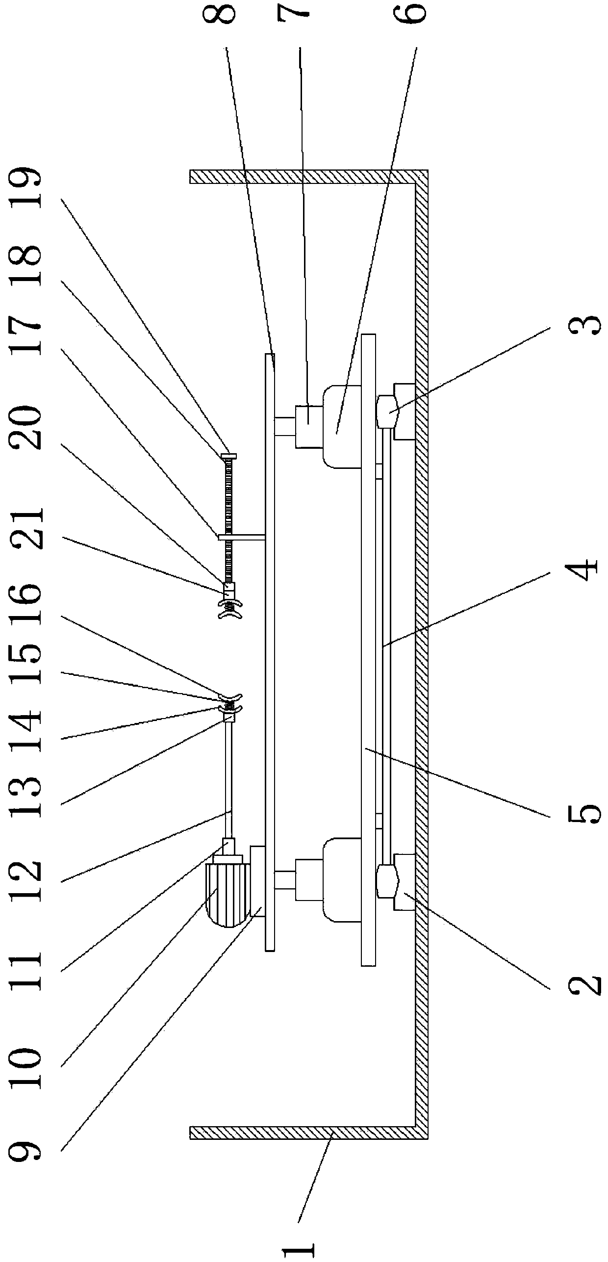
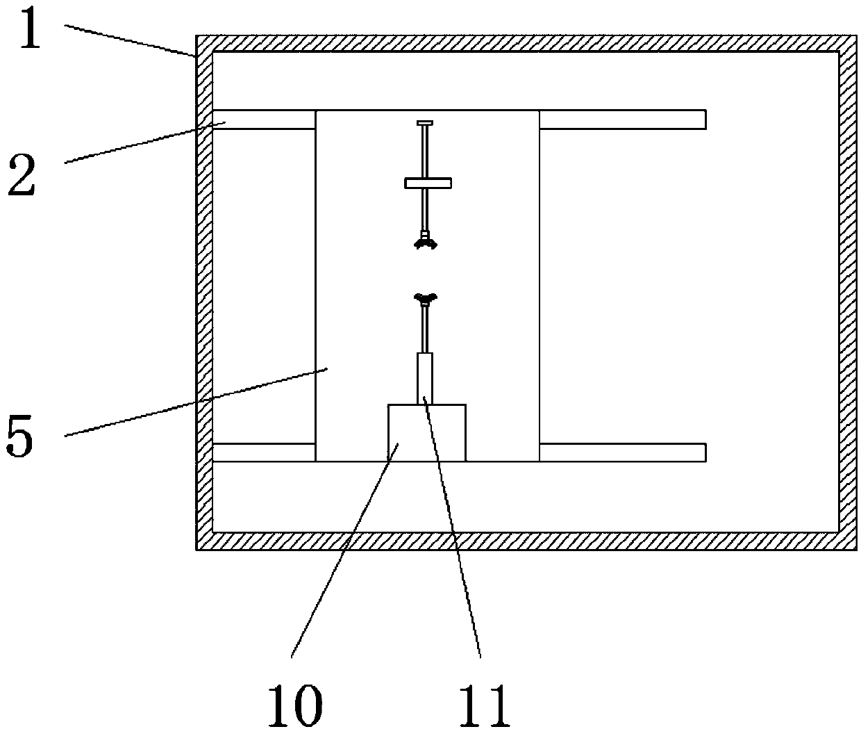
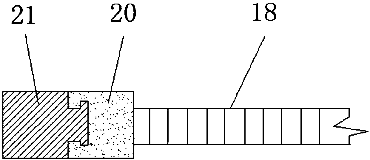
[0019] See Figure 1-3 The present invention provides a technical solution: a clamping device for machine manufacturing, comprising a frame 1 and a vertical plate 17, a slide rail 2 is installed inside the frame 1, and a pulley 3 is provided on the slide rail 2, and the pulley 3 passes The underframe 4 is connected to the bottom of the bottom plate 5. A first motor 6 is provided on the bottom plate 5, and the first motor 6 is connected to a hydraulic rod 7. There are two sets of hydraulic rods 7 and the hydraulic rods 7 are respectively arranged on the horizontal plate 8. The lower two sides enable the horizontal plate 8 to rise and fall smoothly. The hydraulic rod 7 and the horizontal plate 8 are connected to each other, and the horizontal plate 8 is equipped with a backing plate 9, and the backing plate 9 is equipped with a second motor 10 and a second motor 10. A rotating shaft 11 is provided at one end, a rotating rod 12 is installed on the rotating shaft 11, and a connecting block 13 is provided at one end of the rotating rod 12.
[0020] A fixed block 14 is installed on the side of the connecting block 13, and a spring 15 is installed on the fixed block 14, and the top of the spring 15 is provided with a spring pad 16; the fixed block 14 and the spring pad 16 at the upper end of the spring 15 are provided in two groups, and are fixed The spring pads 16 on the block 14 and the spring 15 are respectively arranged on the connecting block 13 and on the movable shaft 21 to facilitate the insertion of parts of different sizes and shapes that need to be clamped. The spring 15 is provided with 3 groups, and the bottom end of the spring 15 is welded On the top of the fixed block 14, and the upper end of the spring 15 and the spring pad 16 are an integral structure, so that the spring 15 is firmly installed on it, and it is not easy to fall when the parts are clamped. The shape of the spring pad 16 and the fixed block 14 are both curved And the diameter of the spring pad 16 and the fixed block 14 are the same, and the material of the spring pad 16 is rubber, and the arc can clamp parts of different shapes. The spring 15 pad is made of rubber, which is non-slip and has frictional force.
[0021] A threaded rod 18 is installed on the vertical plate 17, and one end of the threaded rod 18 is provided with a rotary button 19, and the other end of the threaded rod 18 is installed with a fixed shaft 20, and one side of the fixed shaft 20 is connected with the movable shaft 21, and the fixed shaft 20 sets Embedded on the movable shaft 21, the fixed shaft 20 and the threaded rod 18 are connected by threaded connection, and the movable shaft 21 and the fixed block 14 are connected by welding. When the second motor 10 is working, the movable shaft can be driven by the parts The connecting block 13 on the 21 rotates, and the parts can be polished by changing sides during the grinding of the parts. There is no need to change the sides manually, which saves time.
[0022] Working principle: When using this mechanical clamping device, first fix the frame 1, so that the pulley 3 on the base frame 4 is placed in the slide rail 2, so that the pulley 3 will drive the device on the bottom plate 5 to slide back and forth, which can slide To the required position, the first motor 6 on the bottom plate 5 drives the hydraulic rod 7 up and down, so that the device on the horizontal plate 8 can adjust the position up and down. The second motor 10 is installed on the backing plate 9. After the parts are placed on the spring washer 16 connected to the fixed block 14, the rotary knob 19 can be turned to extend the threaded rod 18 forward, and the fixed shaft 20 on the threaded rod 18 and the movable shaft 21 are sleeved and snapped together to be movable Rotate, and then the spring pad 16 on the fixed shaft 20 will fix the parts to be clamped with the spring pad 16 on the fixed block 14, and then it can be polished. As the parts become smaller during polishing, the spring pad 16 The force of the spring 15 is reduced, which will stretch and squeeze the parts, so that the parts will not fall due to the size of the parts after grinding. When one side of the parts is polished, and then the second motor 10 works, it will drive the rotation on the shaft 11 The rod 12 rotates, and then the connecting block 13 on the rotating rod 12 will also rotate, and then the fixed block 14 is driven, and the fixed block 14 on the fixed shaft 20 is also rotated through the parts, so that the parts can be replaced and polished. , It saves the time of manual replacement of parts and improves work efficiency.
[0023] Although the embodiments of the present invention have been shown and described, those of ordinary skill in the art can understand that various changes, modifications, and substitutions can be made to these embodiments without departing from the principle and spirit of the present invention. And variations, the scope of the present invention is defined by the appended claims and their equivalents.

PUM

no PUM

Description & Claims & Application Information

We can also present the details of the Description, Claims and Application information to help users get a comprehensive understanding of the technical details of the patent, such as background art, summary of invention, brief description of drawings, description of embodiments, and other original content. On the other hand, users can also determine the specific scope of protection of the technology through the list of claims; as well as understand the changes in the life cycle of the technology with the presentation of the patent timeline. Login to view more.

Similar technology patents

Body condition measuring device

InactiveUS20050234351A1simple structure
Owner:DENSO CORP

Magnetic cooling apparatus and control method thereof

ActiveUS20130180263A1simple structure
Owner:SAMSUNG ELECTRONICS CO LTD

Dual-Drivetrain of Power-Assist Vehicle

InactiveUS20100181130A1enhance uphill momentumsimple structure
Owner:CHOU WEN CHENG

Classification and recommendation of technical efficacy words

  • Simple structure
  • easy to use

Sharing system for air-conditioning coat

InactiveCN107440179ASimple structureeasy to wear
Owner:QINGDAO HAIER AIR CONDITIONER GENERAL CORP LTD

Feeding device of sorter of batteries plate

InactiveCN101357717ASimple structurecooperate well
Owner:NANJING NORMAL UNIVERSITY

Emergency parachuting device and method for multiple-rotor unmanned aerial vehicle

InactiveCN103895870Aavoid aircraft crashSimple structure
Owner:SOUTH CHINA AGRI UNIV +1

Laser assisted total joint arthroplasty

InactiveUS20090234360A1easy to use
Owner:ALEXANDER VLADIMIR

Enclosure for a portable hemodialysis system

ActiveUS20090114582A1easy to use
Owner:DEKA PROD LLP
Why Eureka
Try Eureka