Machine manufacturing workbench

A machine manufacturing and workbench technology, applied in the field of machinery, can solve the problems of inability to meet the needs of the machining site work, single function of the workbench, etc., and achieve the effect of simplified structure and convenient use.

Inactive Publication Date: 2018-10-19
XUZHOU MASTER MECHANICAL TECH CO LTD
View PDF0 Cites 3 Cited by
  • Summary
  • Abstract
  • Description
  • Claims
  • Application Information

AI Technical Summary

Problems solved by technology

[0002] At the machining site, the workbench is one of the essential processing equipment. At present, the existing workbench for machining is composed of a rectangular panel and support rods at the four corners below the panel. The function of this workbench is relatively simple. , can no longer meet the work needs of today's machining sites

Method used


Image

  • Machine manufacturing workbench

Examples


Embodiment Construction

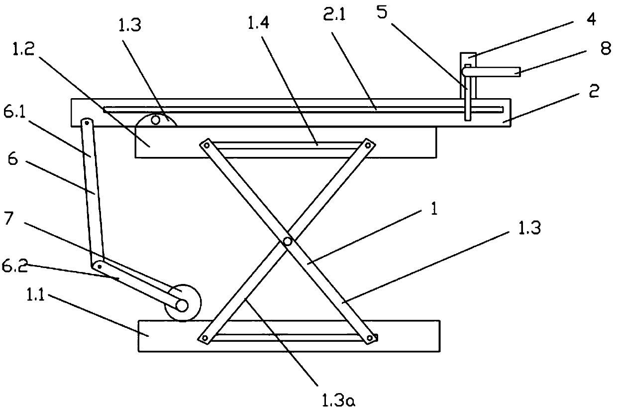
[0011] combined with figure 1 , a mechanical manufacturing workbench, comprising a support frame 1, the support frame 1 includes a bottom frame 1.1, a top frame 1.2 and a lifting assembly 1.3 connected between the bottom frame 1.1 and the top frame 1.2, and the top frame 1.2 is provided with There is a working platform 2, one end of the top frame 1.2 is movably connected to the bottom of the working platform 2 through a rotating part 3, the upper part of the working platform 1.3 is provided with a slidable scraper 4, and the two ends of the slidable scraper 4 are connected by a sliding bar 5 is movably connected with both sides of the working platform 2, the end of the working platform 2 close to the rotating part 1.3 is provided with a tie rod assembly 6, and the bottom frame 1.1 is provided with a driving device 7 for driving the pull rod assembly 6.

[0012] As a preferred implementation of this embodiment, the lifting assembly 1.3 includes several support rods 1.3a arrange...


PUM


Abstract

The invention discloses a machine manufacturing workbench. The machine manufacturing workbench comprises a supporting framework, and the supporting framework comprises a bottom frame, a top frame anda lifting assembly connected between the bottom frame and the top frame; the top frame is provided with a working platform, one end of the top frame is movably connected with the bottom of the workingplatform through a rotating piece, the upper part of the working platform is provided with a slidable scraping plate, the two ends of the slidable scraping plate are movably connected with the two sides of the working platform through sliding rods, the end, close to the rotating piece, of the working platform is provided with a pull rod assembly, and a driving device for driving the pull rod assembly is arranged on the bottom frame. According to the machine manufacturing workbench, the height of the workbench can be adjusted through the lifting assembly, and the angle of the workbench can beadjusted through the pull rod assembly so that waste material and rubbish on the surface of the workbench can be cleared under the cooperation of the slidable scraping plate in a relative convenient mode; and the machine manufacturing workbench is simple in structure and convenient to use and is suitable for practical production.

Description

technical field [0001] The invention relates to the technical field of machinery, in particular to a machine manufacturing workbench. Background technique [0002] At the machining site, the workbench is one of the essential processing equipment. At present, the existing workbench for machining is composed of a rectangular panel and support rods at the four corners below the panel. The function of this workbench is relatively simple. , can no longer meet the work needs of today's machining sites. Contents of the invention [0003] In order to solve the above technical problems, the technical solution provided by the present invention is: a mechanical manufacturing workbench, including a support frame, the support frame includes a bottom frame, a top frame, and a lifting assembly connected between the bottom frame and the top frame. A working platform is provided on the top frame, and one end of the top frame is movably connected to the bottom of the working platform throu...

Claims


Application Information

Patent Timeline
IPC IPC(8): B25H1/02B25H1/16B25H1/18B08B1/00
CPCB25H1/02B25H1/16B25H1/18B08B1/165B08B1/30
Inventor 郭楠肖彩
Owner XUZHOU MASTER MECHANICAL TECH CO LTD
Why Eureka
Try Eureka