Mechanical arm used for numerical control machine tool

A technology of CNC machine tools and mechanical arms, applied in the field of mechanical arms, can solve the problems of inconvenient maintenance and repair, damage to workpieces, limited moving range, etc., and achieve the effects of easy maintenance and repair, avoiding damage to workpieces, and increasing the working range

Inactive Publication Date: 2018-10-19
杨辉宜
View PDF0 Cites 4 Cited by
  • Summary
  • Abstract
  • Description
  • Claims
  • Application Information

AI Technical Summary

Problems solved by technology

[0002] The mechanical arm for CNC machine tools is an auxiliary tool for CNC machining. It can replace manual work to complete various dangerous tasks and work for a long time, and gradually replaces manual operations. Therefore, it has gradually received widespread attention from people. The mechanical arms for machine tools cannot meet the needs of people; the existing mechanical arms for CNC machine tools have certain disadvantages when they are used. It is convenient for later maintenance and repair. Secondly, the working range of the mechanical arm cannot be increased, and the moving range is limited, which is not convenient for the use of CNC machine tools. Finally, it is not possible to buffer and protect the clamped workpiece, which is not convenient for better protection of the workpiece. , it is easy to damage the workpiece due to excessive clamping force, which has a certain impact on people's use process. Therefore, we propose a mechanical arm for CNC machine tools

Method used


Image

  • Mechanical arm used for numerical control machine tool
  • Mechanical arm used for numerical control machine tool
  • Mechanical arm used for numerical control machine tool

Examples


Embodiment Construction

[0017] In order to make the technical means, creative features, goals and effects achieved by the present invention easy to understand, the present invention will be further described below in conjunction with specific embodiments.

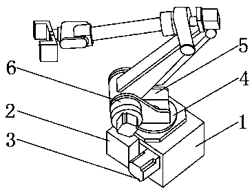
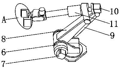
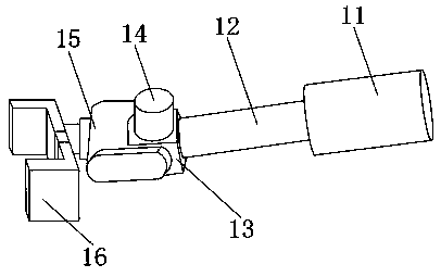
[0018] Such as Figure 1-4 As shown, a mechanical arm for a numerically controlled machine tool includes a base 1, an electric control box 2, and a No. 1 motor 3. On one side of the No. 1 motor 3, a turntable 4 is arranged on the outer surface of the upper end of the base 1, a chassis 5 is arranged on the upper end of the turntable 4, a rotating shaft 6 is arranged on one side of the upper end of the chassis 5, and a balance cylinder 7 is fixedly installed on one side of the rotating shaft 6 , the upper end of the rotating shaft 6 is provided with a support arm 8, the outer surface of the lower end of the support arm 8 is fixedly installed with a wire groove 9, and the outer surface of the upper end of the support arm 8 is fixedly installed with a...


PUM


Abstract

The invention discloses a mechanical arm used for a numerical control machine tool. The mechanical arm includes a base, an electronic control box and a first motor; the electric control box and the first motor are both located on the outer surface of one side of the base, and the electronic control box is located on one side of the first motor; and a rotating disk is arranged on the outer surfaceof the upper end of the base, a bottom disk is arranged at the upper end of the rotating disk, and a rotating shaft is arranged on one side of the upper end of the bottom disk. According to the mechanical arm used for the numerical control machine tool, a wire groove, a telescopic rod and buffer blocks are arranged, the complex lines of the mechanical arm can be classified and organized, winding caused by the tedious lines is avoided, the maintenance and repair at the later stage are facilitated, the working range of the mechanical arm can be increased, all-round movement is achieved, and thenumerical control machine tool can be used conveniently; and buffer protection can be conducted on the clamped workpieces, the workpieces are convenient to better protect and prevented from being damaged due to the excessive clamping force, and the mechanical arm has a certain practicality and brings better using prospects.

Description

technical field [0001] The invention relates to the field of mechanical arms, in particular to a mechanical arm for a numerically controlled machine tool. Background technique [0002] The mechanical arm for CNC machine tools is an auxiliary tool for CNC machining. It can replace manual work to complete various dangerous tasks and work for a long time, and gradually replaces manual operations. Therefore, it has gradually received widespread attention from people. The mechanical arms for machine tools cannot meet the needs of people; the existing mechanical arms for CNC machine tools have certain disadvantages when they are used. It is convenient for later maintenance and repair. Secondly, the working range of the mechanical arm cannot be increased, and the moving range is limited, which is not convenient for the use of CNC machine tools. Finally, it is not possible to buffer and protect the clamped workpiece, which is not convenient for better protection of the workpiece. ,...

Claims


Application Information

Patent Timeline
Patent Type & Authority Applications(China)
IPC IPC(8): B25J9/00B25J19/00B25J18/02B23Q7/00
CPCB25J9/0096B23Q7/00B25J9/0009B25J18/025B25J19/00B25J19/0008
Inventor 杨辉宜
Owner 杨辉宜
Why Eureka
Try Eureka