Automatic precision rotary cutting machine

A rotary cutting machine, precise technology, applied in the direction of forming/shaping machine, special forming/shaping machine, thin wood chip manufacturing, etc., can solve the problems of intermittent waste of wood chips, poor quality of wood chips, and unfavorable continuous production.

Active Publication Date: 2018-10-19
漳州市炯辉机械有限公司
View PDF6 Cites 17 Cited by
  • Summary
  • Abstract
  • Description
  • Claims
  • Application Information

AI Technical Summary

Problems solved by technology

[0002] The existing high-precision rotary cutting machines are generally large in size and complex in structure. Before the machine is used, the logs need to be centered. If the centering is not accurate, intermittent veneer strips or narrow veneers will be unscrewed when the rotary cutting is started.
The more broken veneers or narrow veneers, the more good sapwood veneers are lost, which is not conducive to continuous production
[0003] The prior art discloses a high-precision wood processing rotary cutting machine with an application number of 201621000309.1, which includes a rear side plate, a frame, a cylinder, a first inclined plate, a strut, an abutment, a first sliding sleeve, and a first movable Rods, rollers, first springs, buttons, support rollers, etc.; the bottom of the front side of the rear side plate is provided with a frame, and the top of the frame is sequentially provided with a first slant plate, a support rod and an abutment from left to right, and the first slant plate The bottom end is hingedly connected to the top of the frame, and the lower part of the left wall in the frame is inclined to be provided with a cylinder, and the bottom of the cylinder is hingedly connected to the left wall inside the frame, but this prior art lacks a centering function and cannot automatically move logs. Alignment may lead to poor quality of wood chips produced by rotary cutting, especially intermittent waste of wood chips, which increases the economic cost of raw materials

Method used


Image

  • Automatic precision rotary cutting machine
  • Automatic precision rotary cutting machine
  • Automatic precision rotary cutting machine

Examples


Embodiment Construction

[0034] In order to further explain the technical solutions of the present invention, specific examples are given below to illustrate in detail.

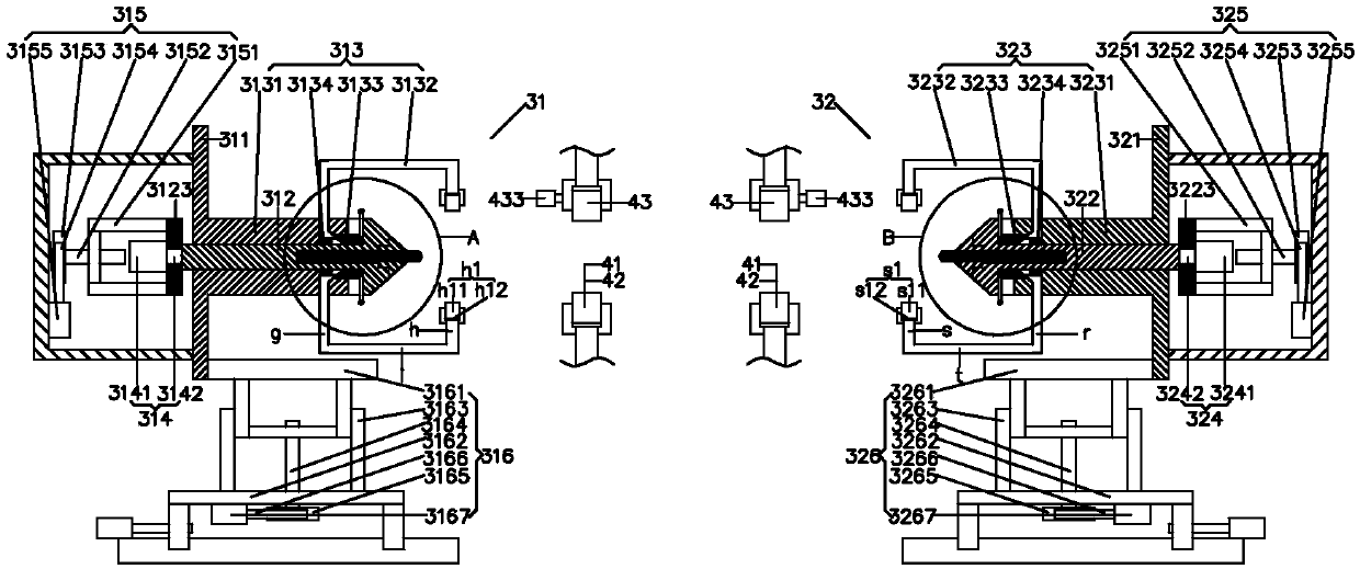
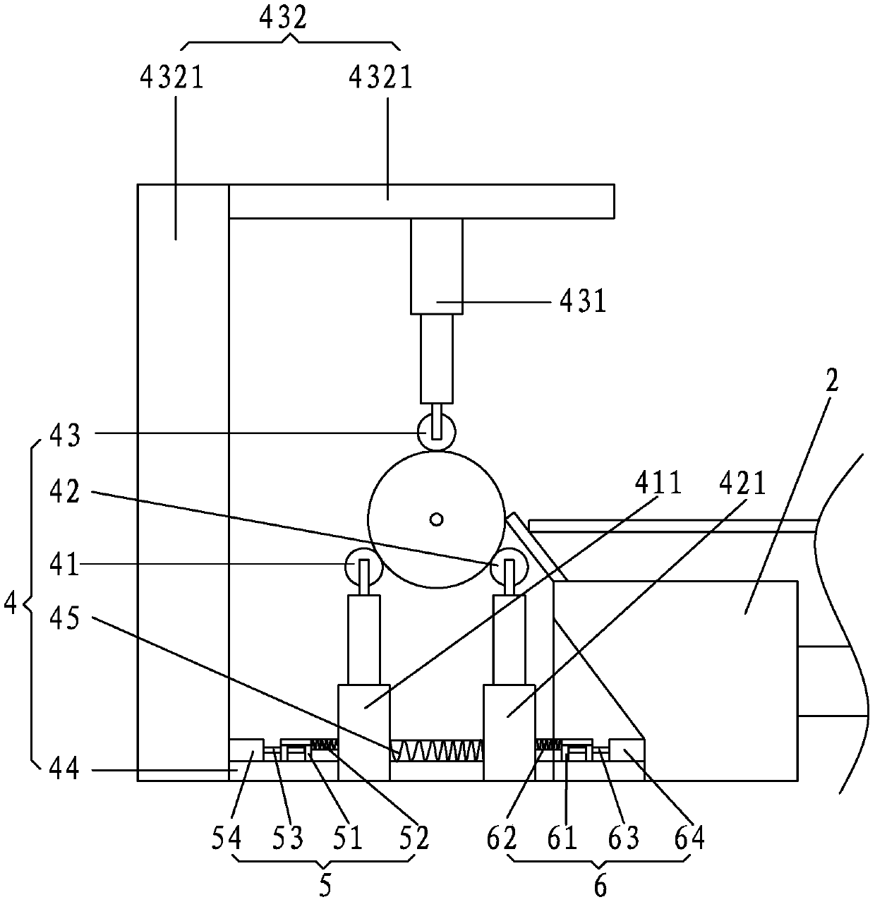
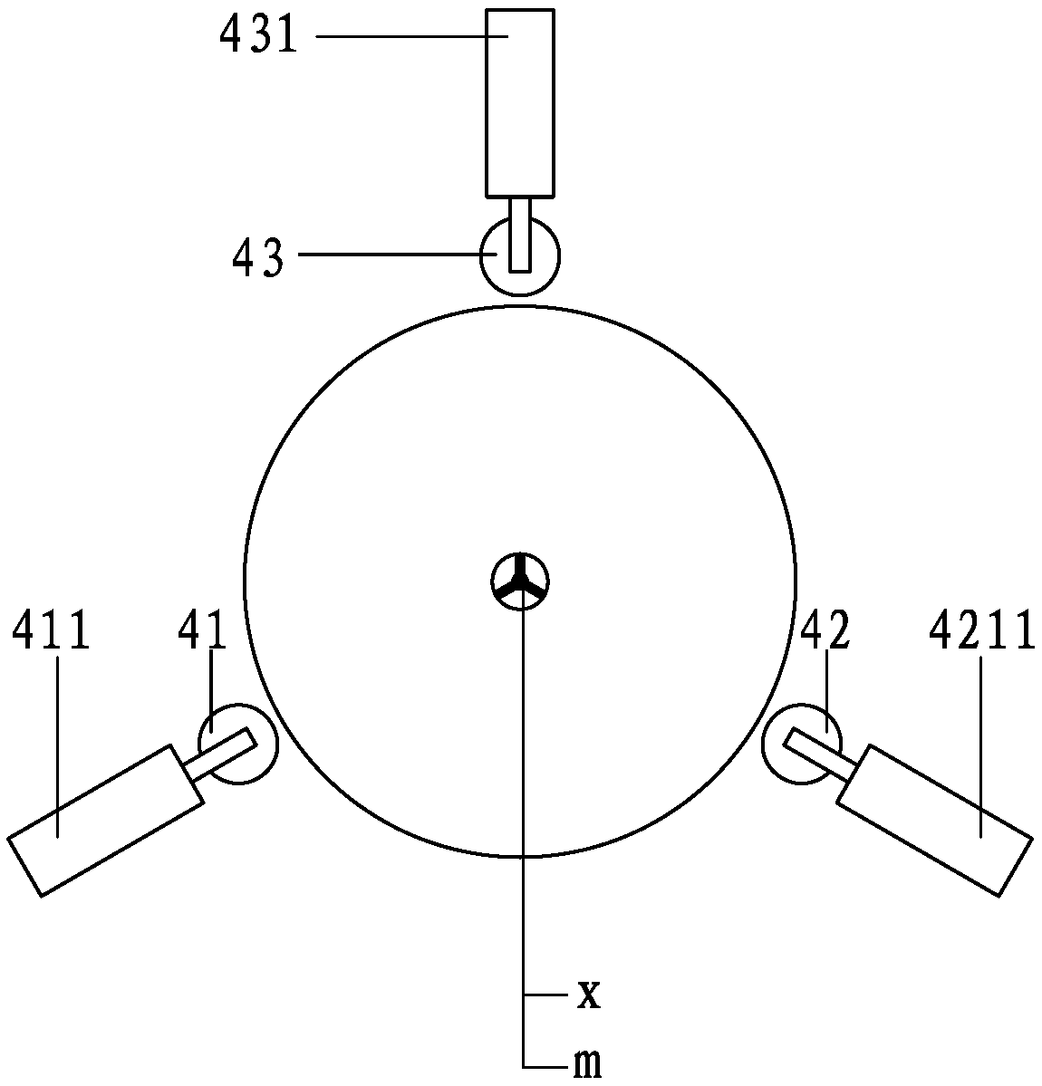
[0035] A kind of automatic precision rotary cutting machine of the present invention, as Figure 1-6 As shown, it includes a frame, a rotary cutting device 2 and a clamping shaft located on the frame; the clamping shaft includes a first clamping portion 31 at one end of the log, and a second clamping portion 32 at the other end of the log; Both the first clamping part 31 and the second clamping part 32 have a proximal end facing the direction of the log and a distal end facing the opposite direction; it is characterized in that it also includes a positioning and rotating drive device 4 for positioning and rotating the log;

[0036] The first clamping part 31 includes a first main base plate 311 perpendicular to the log, a first positioning shaft device passing through the first main base plate 311, and a first positioning sleeve devi...


PUM


Abstract

The invention puts forwards an automatic precision rotary cutting machine. Before a rotary cutting device begins to perform rotary cutting, a first lifting driving device slides away from a second clamping part along a first horizontal guiding rail, a first lower telescopic supporting rod and a second lower telescopic supporting rod slide to make contact with a log in an abutting manner, the log is supported to abut against an upper driving wheel single body, a first advancing and retreating motor drives a first rotating shaft to move away from a second clamping part, a first lifting frame moves to the height, corresponding to the circle center of the log, of a first cutter, a worker rotates a first operating handle for adjustment, the first clamping arm clamps the log, a controller controls driving of a first lifting motor, the pressure applied by a first main base plate to the first lifting frame before the log is clamped is equal to the pressure after the log is clamped, the first lifting driving device slides towards the second clamping part along the first horizontal guiding rail, the first rotating shaft moves towards the second clamping part, and the first cutter is automatically aligned to the log.

Description

technical field [0001] The invention relates to the field of rotary cutting machinery, in particular to an automatic precision rotary cutting machine. Background technique [0002] Existing high-precision rotary cutting machines are generally large in size and complex in structure, and the logs need to be centered before being put on the machine. If the centering is not accurate, intermittent veneer strips or narrow veneers will be unscrewed when the rotary cutting starts. The more broken veneers or narrow veneers, the more good sapwood veneers are lost, which is not conducive to continuous production. [0003] The prior art discloses a high-precision wood processing rotary cutting machine with an application number of 201621000309.1, which includes a rear side plate, a frame, a cylinder, a first inclined plate, a strut, an abutment, a first sliding sleeve, and a first movable Rods, rollers, first springs, buttons, support rollers, etc.; the bottom of the front side of the ...

Claims


Application Information

Patent Timeline
Patent Type & Authority Applications(China)
IPC IPC(8): B27L5/02B27C5/00
CPCB27C5/00B27L5/02
Inventor 黄泽辉
Owner 漳州市炯辉机械有限公司
Why Eureka
Try Eureka