Automobile radiator shock pad

An automobile radiator and shock-absorbing pad technology, which is applied to the arrangement of vehicle components and power unit cooling combination, power unit and other directions, can solve the problem that the radiator mounting pin is difficult to insert into the shock-absorbing pad, the practical load-bearing capacity is insufficient, and the structure is not reasonable enough. and other problems, to achieve the effect of improving shipping efficiency and installation efficiency, large bearing capacity, and preventing falling off.

Pending Publication Date: 2018-10-19
重庆市涪陵区李渡星耀橡塑有限公司
View PDF6 Cites 4 Cited by
  • Summary
  • Abstract
  • Description
  • Claims
  • Application Information

AI Technical Summary

Problems solved by technology

[0003] However, there are the following problems in the connection and cooperation between the existing shock pad and the radiator mounting pin: one, if the internal through hole of the shock pad is an interference fit with the radiator mounting pin, the radiator mounting pin is difficult to insert into the shock pad. In the internal through hole; second, if the internal through hole of the shock pad and the mounting pin are clearance fit, the radiator is easy to fall off during transportation and vehicle assembly process, and it is difficult to locate on the vehicle
At the same time, the existing shock absorbing pads have contradictions in rubber hardness, vibration isolation efficiency and service life. If the rubber hardness is high, the vibration isolation effect will be insufficient. If the rubber hardness is small, there will be insufficient practical load-bearing capacity. The problem is that the service life is short, and the existing shock pads are heavy and the structure is not reasonable enough

Method used


Image

  • Automobile radiator shock pad
  • Automobile radiator shock pad
  • Automobile radiator shock pad

Examples


Embodiment Construction

[0022] The present invention will be further described in detail below with reference to the drawings and specific embodiments, so that those skilled in the art can understand.

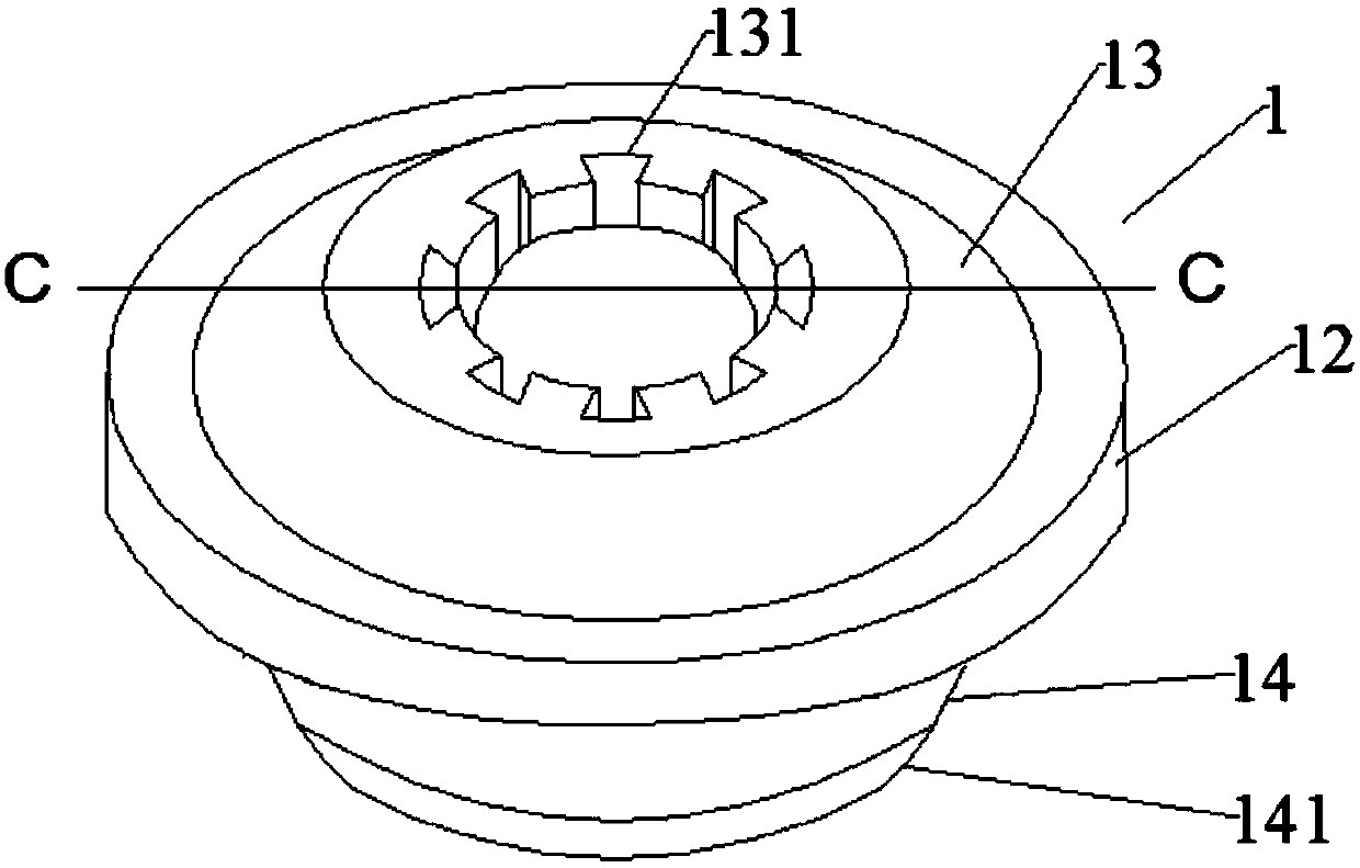
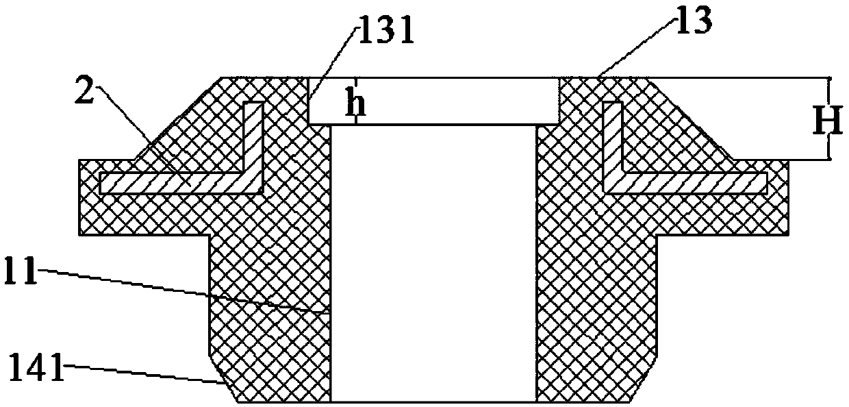
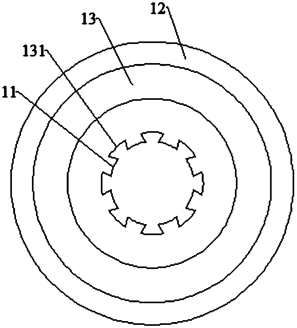
[0023] Figure 1-3 Shown is the automobile radiator shock absorber of the present invention, comprising an integrally formed shock absorber body 1 with an axial through hole 11 in the center, the shock absorber body 1 includes a disc body 12, and a disc body 12 The upper mounting round platform 13 connected with the upper end surface and the lower mounting cylinder 14 connected with the lower end surface of the disc body 12, the axis line of the disc body 12, the upper mounting round platform 13 and the lower mounting cylinder 14 is in line with the axial through hole 11 have the same center line, and the upper end surface of the upper mounting round platform 13 is provided with a plurality of tooth grooves 131 communicating with the axial through hole 11 and uniformly distributed radially outward alo...


PUM


Abstract

The invention discloses an automobile radiator shock pad. The automobile radiator shock pad comprises an integrally-formed shock pad body with an axial through hole formed in the center. The shock padbody comprises a disc body, an upper installation truncated cone connected with the upper end face of the disc body and a lower installation cylinder connected with the lower end face of the disc body. The upper end face of the upper installation truncated cone is provided with multiple tooth grooves communicating with the axial through hole and evenly distributed outwards in the radial directionof the upper installation truncated cone. A metal framework is buried between the disc body and the upper installation truncated cone. The automobile radiator shock pad capable of meeting the requirements for load bearing, shock absorption and assembling of a radiator is provided, and ride comfort is improved.

Description

1. Technical field [0001] The invention relates to an automobile radiator installation structure, in particular to an automobile radiator shock absorber. 2. Background technology [0002] At present, the shock absorbing pads of automobile radiators are all made of rubber materials. The main function is to support and limit the relative movement of the automobile radiator. The shock absorption effect improves the ride comfort of the vehicle. Furthermore, the shock pad can also protect the radiator, preventing the radiator from being damaged due to too much external pressure. [0003] However, there are the following problems in the connection and cooperation between the existing shock pad and the radiator mounting pin: one, if the internal through hole of the shock pad is an interference fit with the radiator mounting pin, the radiator mounting pin is difficult to insert into the shock pad. The second is that if the internal through hole of the shock pad and the mounting pin...

Claims


Application Information

Patent Timeline
Patent Type & Authority Applications(China)
IPC IPC(8): B60K11/04F16F15/08
CPCF16F15/08B60K11/04
Inventor 朱世勇
Owner 重庆市涪陵区李渡星耀橡塑有限公司
Why Eureka
Try Eureka