Elastic strip fastener structure for small-radius track steel rail

A small-radius, steel-rail technology, used in rails, fixed rails, roads, etc., can solve problems such as difficulty in maintaining stable track geometry, increase line maintenance costs, and severe wear and tear of track components, to avoid falling off or theft and loss, The effect of improving safety and reliability and reducing maintenance costs

Pending Publication Date: 2018-10-19
中原利达铁路轨道技术发展有限公司
View PDF0 Cites 0 Cited by
  • Summary
  • Abstract
  • Description
  • Claims
  • Application Information

AI Technical Summary

Problems solved by technology

However, the radius of curvature of the small-radius curved track is small. When the train passes in a forced inscribed manner, a huge interaction force is generated between the wheel and the rail, which makes it difficult to maintain a stable geometric state of the track, and it is easy to cause many diseases such as severe wear of the track components, especially The rails outside the curve are frequently replaced due to excessive wear on the side, which greatly increases the maintenance cost of the line
In order to strengthen the structural strength of the small-radius curved track, slow down the side wear of the rail, prolong the service life of the track, and improve the safety and reliability of train passage, adjustments must be made during the construction of the rail. The existing fasteners can no longer meet the construction requirements.

Method used


Image

  • Elastic strip fastener structure for small-radius track steel rail
  • Elastic strip fastener structure for small-radius track steel rail
  • Elastic strip fastener structure for small-radius track steel rail

Examples


Embodiment 1

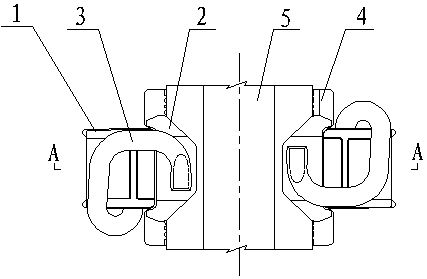
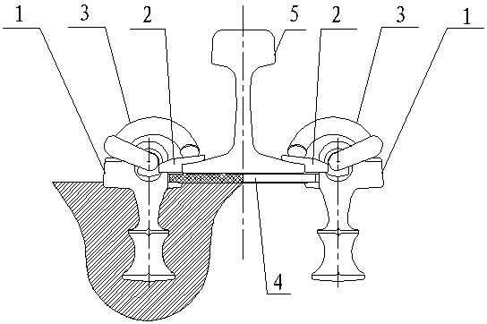
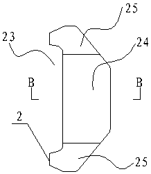
[0036] Such as Figure 1 to Figure 13 As shown, a spring-bar fastener structure for small-radius rails of the present invention includes rails 5 installed on the rails of sleepers in the front-to-back direction. The rails of the sleepers are located on the left and right sides of the rails 5. There are embedded fixed seat 1. The pre-embedded fixing seat 1 and the corresponding side surface of the steel rail 5 are fitted with a gauge stopper 2 to provide insulation and fixation. The inner side of the gauge stop 2 is provided with a protrusion 21 extending inward and laying on the upper side of the rail bottom. The protrusion 21 is provided with a downwardly protruding jaw 22 and cooperates with the protrusion 21 to form a card slot , The rail bottom of the steel rail 5 is clamped in the slot; the outer side of the gauge block 2 is set as a bayonet 23 that matches the corresponding embedded fixing seat, and the gauge block 2 passes through the bayonet 23 and the corresponding pre...

Embodiment 2

[0048] Such as Figure 14 to Figure 15 As shown, the difference between this embodiment and the first embodiment is that: an anti-theft structure is provided between the support portion of the e-shaped elastic bar 3 and the embedded fixing seat 1, and the anti-theft structure includes the lower side of the supporting portion of the e-shaped elastic bar 3 The anti-returning protrusion 6 and the positioning recess 7 provided on the upper side of the embedded fixing seat, the anti-returning protrusion 6 is engaged with the positioning recess 7; and along the length direction of the support portion of the e-shaped elastic strip 3, The anti-return protrusion 6 is divided into the installation forward side and the disassembly backward side. The installation forward side 61 of the anti-return protrusion 6 and the e-shaped elastic bar are smoothly transitioned, and the disassembly rear side 62 of the anti-return protrusion 6 and the e-shaped elastic bar form a stop Retreat the facade. ...


PUM

PropertyMeasurementUnit
Insulation resistanceaaaaaaaaaa

Abstract

The invention discloses an elastic strip fastener structure for a small-radius track steel rail. The elastic strip fastener structure comprises the steel rail mounted on the rail bearing surface of asleeper in the front-rear direction. Pre-embedded fixing seats are arranged on the positions, on the left side and the right side of the steel rail, of the rail bearing surface of the sleeper correspondingly; gauge stop blocks are arranged between the pre-embedded fixing seats and the corresponding side faces of the steel rail in a clamped mode correspondingly, protruding parts extending inwards and erected on the upper side of the rail bottom of the steel rail are arranged on the inner sides of the gauge stop blocks, jaw parts protruding downwards are arranged at the protruding parts, and thejaw parts and the protruding parts are matched to form clamping grooves; and the rail bottom of the steel rail is connected into the clamping grooves in a clamped mode; clamping openings matched withthe corresponding pre-embedded fixing seats are formed in the outer sides of the gauge stop blocks, and the gauge stop blocks are matched with the corresponding pre-embedded fixing seats through theclamping openings in a clamped connection mode; and e-shaped elastic strips are further mounted on the pre-embedded fixing seats, buckle-pressing parts of the e-shaped elastic strips are arranged on the gauge stop blocks in a pressed mode, and supporting parts of the e-shaped elastic strips are matched with the pre-embedded fixing seats in a jacking connection mode. The elastic strip fastener structure for the small-radius track steel rail is convenient to mount and stable in structure, and the mounted track structure strength is ensured.

Description

Technical field [0001] The invention relates to the technical field of railway engineering, in particular to a spring bar fastener structure used for small radius track rails. Background technique [0002] At present, railway transportation is developing rapidly around the world. As a basic component of the railway track system, fasteners play the role of fixing the rails and adjusting the gauge, while providing a buffer for the track system to improve the comfort of the train. The amount of fasteners on the railway line is large, and the maintenance cost is high. Therefore, simple structure, high strength, and lower maintenance costs have always been the development direction of fasteners. [0003] In the construction of the railway, there are more connections with small radius circular curves. The small-radius curved track has a small curvature radius. When the train passes in a forced inward connection mode, a huge interaction force is generated between the wheel and the rail,...

Claims


Application Information

Patent Timeline
IPC IPC(8): E01B9/30
CPCE01B9/30
Inventor 刘惠敏牛检伟
Owner 中原利达铁路轨道技术发展有限公司
Why Eureka
Try Eureka