Strip mine continuous mining system

It is an open-pit mine and continuous technology, which is applied in open-pit mine mining, earth drilling, special mining, etc. It can solve the problems of huge maintenance workload, high procurement cost, and low mining efficiency, and achieve low procurement and management costs. The effect of simple structure and wide adaptability to conditions

Pending Publication Date: 2018-10-19
SHANGHAI BRANCH TIANDI SCI&TECH CO LTD +1
View PDF0 Cites 3 Cited by
  • Summary
  • Abstract
  • Description
  • Claims
  • Application Information

AI Technical Summary

Problems solved by technology

For the mining of thick ore seams, a large number of single-bucket excavators (such as hydraulic shovels and electric shovels) are currently used for mining, and at the same time, they are equipped with car transportation, crushers, and belt conveyors. Due to the large number of auxiliary supporting equipment in the working face, the maintenance workload is huge. , single bucket shovel excavator and supporting system, this kind of discontinuous mining system, the problem of high mining cost per ton of material and low mining efficiency is becoming more and more serious
With the development of technology and the emergence of extra-thick ore seams, giant bucket-wheel excavators, supporting mobile crushers and mobile loaders have gradually been developed. Although this type of near-continuous mining can adapt to the efficient mining of extra-thick ore seams, the The cost is huge, and it is very uneconomical for the mining of ore layers below medium thickness, which cannot meet the needs of some small and medium mines

Method used


Image

  • Strip mine continuous mining system
  • Strip mine continuous mining system
  • Strip mine continuous mining system

Examples


Embodiment Construction

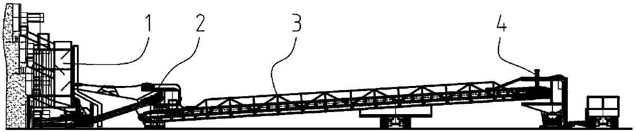
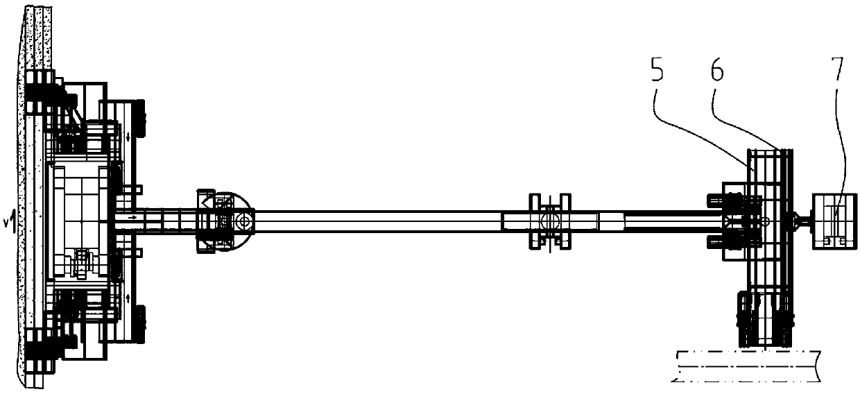
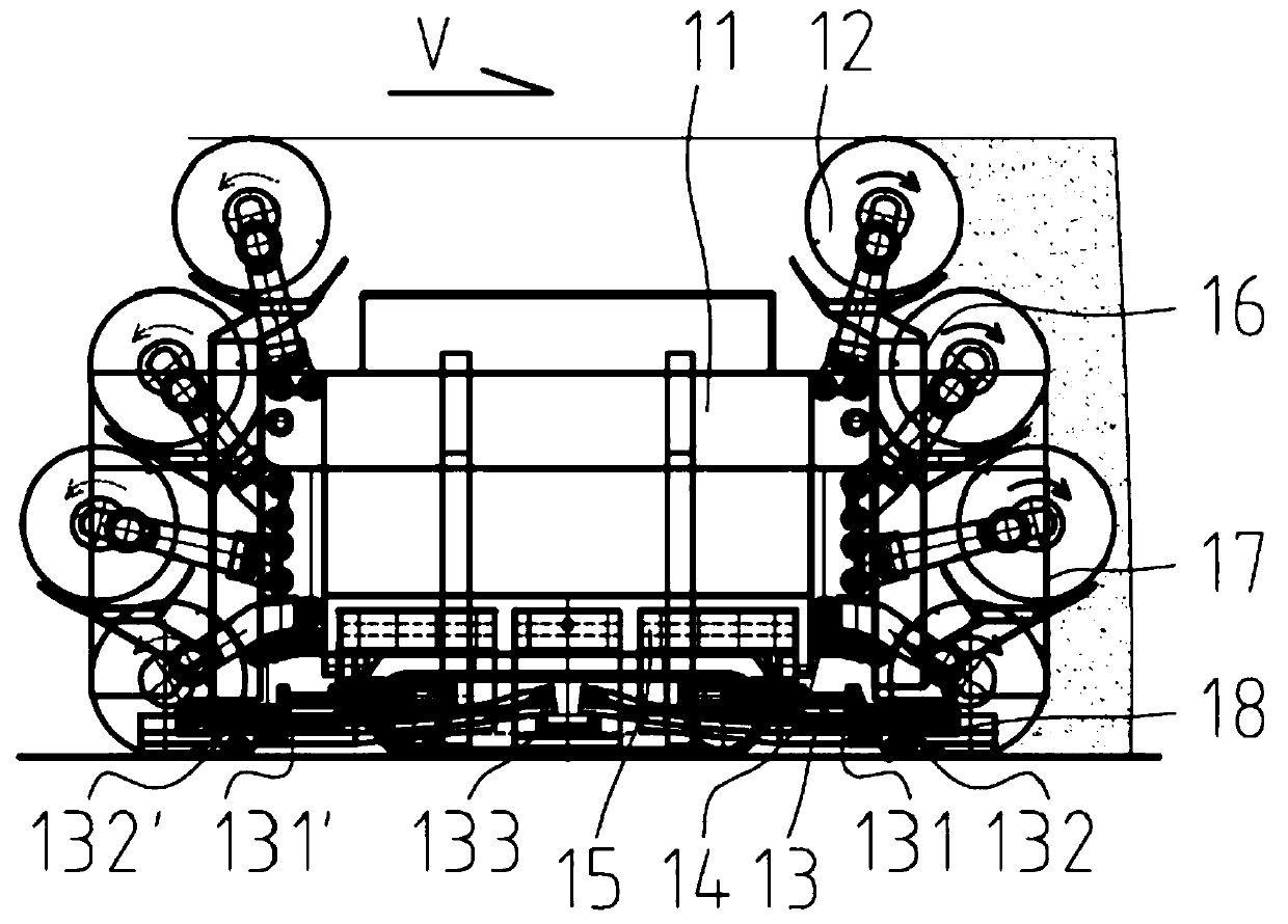
[0046] Such as Figures 1a-8b As shown, the present invention discloses a continuous mining system for an open-pit mine, which includes a mining machine 1 , a transfer conveyor 3 and a working face conveyor 5 . The rear end of the intermediate conveying device 133 of the mining machine is hinged with the front end of the reloading conveyor through the front-stage connection mechanism 2, the hinge axis extends vertically, and the rear end of the intermediate conveying device of the mining machine is located at the reloading conveyor. above the front end of the conveyor. At least one place below the main body of the transfer conveyor is provided with universal wheels. The rear end of the transfer conveyor is hinged to a rear-stage connecting mechanism 4, and the hinge axis extends vertically. The rear connecting mechanism is provided with a rear receiving hopper, the latter is located below the rear end of the transfer conveyor, and the discharge port of the latter is located ...


PUM


Abstract

The invention relates to a strip mine continuous mining system. The strip mine continuous mining system comprises a mining machine, a transfer loading conveyor and a working face conveyor, the rear end of a middle conveying device of the mining machine is hinged with the front end of the transfer loading conveyor through a front-stage connection mechanism, the hinging axis extends vertically, therear end of the middle conveying device is located on the upper position, universal wheels are arranged at at least one position below the main body of the transfer loading conveyor, the rear end of the transfer loading conveyor is hinged with a back-stage connection mechanism, the hinging axis extends vertically, the back-stage connection mechanism is provided with a back-stage material receivinghopper, the back-stage material receiving hopper is located below the rear end of the transfer loading conveyor, an unloading port of the back-stage material receiving hopper is located above the working face conveyor, the working face conveyor extends left and right, and the back-stage connection mechanism is slidably connected relative to the left and right directions of the working face conveyor. The strip mine continuous mining system can achieve all procedures of cutting, collecting, conveying in a host machine, transfer loading, working face conveying and the like, is low in purchasingand management cost, easy to maintain, and particularly suitable for mining small and medium-sized mine ore deposits.

Description

technical field [0001] The invention relates to an open-pit mine continuous mining system, which belongs to the technical field of mining machinery. Background technique [0002] The conditions of different working faces of open-pit mines vary greatly, such as the thickness of some meters, some tens of meters, and the corresponding equipment is different. For the mining of thick ore seams, a large number of single-bucket excavators (such as hydraulic shovels and electric shovels) are currently used for mining, and at the same time, they are equipped with car transportation, crushers, and belt conveyors. Due to the large number of auxiliary supporting equipment in the working face, the maintenance workload is huge. The problems of high mining cost per ton of material and low mining efficiency are becoming more and more serious in the non-continuous mining system of single bucket excavator and supporting system. With the development of technology and the emergence of extra-th...

Claims


Application Information

Patent Timeline
Patent Type & Authority Applications(China)
IPC IPC(8): E21C47/00E21C35/22E21C29/22
CPCE21C47/00E21C29/22E21C35/22
Inventor 贠瑞光章立强周常飞王振乾郭岱胡璟胡滔阚文浩董超宋振冯大盛顾恩洋张晓永
Owner SHANGHAI BRANCH TIANDI SCI&TECH CO LTD
Why Eureka
Try Eureka